
Executive Summary
The purpose of this project was to create a mechanical system that integrated various techniques we had acquired throughout the course, Mechanical Prototyping, including manipulating sheet metal, 3D printing, casting polymers, and surface finishing. Specifically, Team Phillipp sought to achieve this through the design and construction of a functional moving Möbius mechanism. We drew inspiration from our instructor’s original design but diverged from the actual design with our conclusion that having stationary gears that rotated the Möbius strip would be more effective.
Structure
Möbius Strip
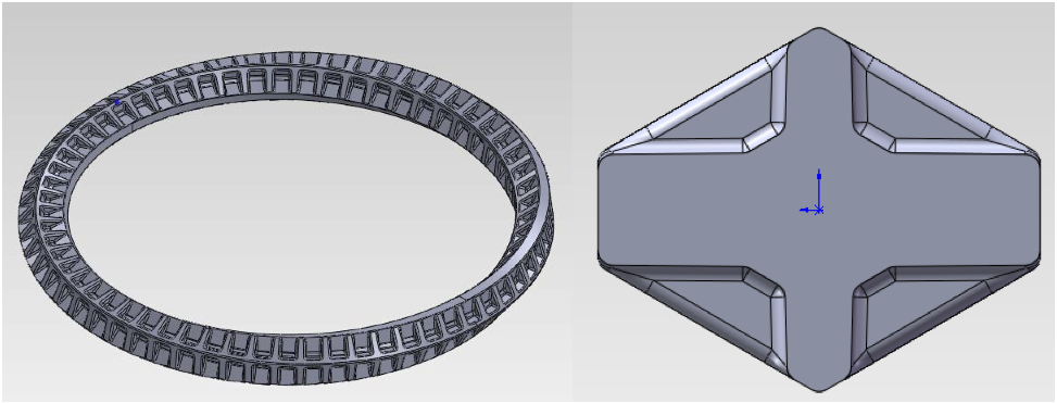
The Möbius strip was constructed by performing two sweeps 180 degrees apart and having each swept loft rotate 90 degrees. The strip is 6” in diameter, has a width of 0.6”, and a height of 0.5”. The gear track was created by offsetting a plane from the face of the strip and creating a lofted cut from the face of the strip to the new plane.
The profile of the strip is similar to a V belt. This design, along with the shape of the gear discussed later in this paper, prevents the strip from slipping out between the gears. This also provides more surface area between the gears and the strip.
Möbius Strip Molds
The Möbius strip had to be flexible and compliant enough to rotate to different angles through the gears. At the same time, the strip had to be sturdy enough such that it retained the pattern of the gear track and allowed the gears to push it along without drooping. We decided that the urethane rubber VytaFlex 40 polymer had the necessary characteristics we sought for our Möbius strip.
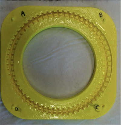
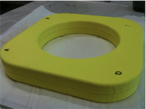
The Möbius strip molds were made by extruding a box around the Möbius strip in Solidworks. The Möbius strip was then subtracted from the extruded box. The mold was then cut in half. Pegs were added to the top half and holes were added to the bottom half to ensure that the molds were aligned correctly. The pegs were tapered to facilitate putting the two halves together.
The pegs were not labeled, so we had to determine after the RP print which pegs matched which holes. Fortunately the center hole was offset and it was fairly simple to figure out the correct orientation of the molds and label them. Epoxamite was applied to the mold to seal the RP filaments. The mold was also shellac‐ed before pouring so that the polymer would not adhere to the mold.
First the VytaFlex 40 was prepared and poured into both halves of the mold, which were subsequently vacuumed in a Vic 12 vacuum, as shown in Figure 3. The vacuum removed the air pockets from the polymer in the mold due to the excessive amount of undercuts. After the polymers had partly cured, more VytaFlex 40 was prepared and applied to the semi‐cured polymer. The mold was then clamped to the table and allowed to cure for 24 hours.
After the polymer was cured, attempts were made to pry open the mold. Since this did not work, the mold was sawn and chiseled away, resulting in the strip shown in Figure 7. In the future, the body of the mold would be smaller and shelled to facilitate removal of the mold.
Gear Stands
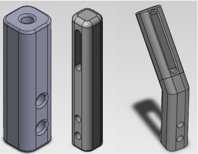
The gear stands were designed to be printed on the RP machine. The original designs are shown on the left. However, the stands were not printed correctly, so sheet metal variations were constructed due to time constraints. These stands retained the same characteristics as their RP counterparts would have had – holes of attachment and slots for adjustable gear positioning.
There were a total of 8 gears in our design. The gears are paired together to hold the strip from above and below. Two of the gears are mounted directly to the servo horns while the other six gears are mounted on the gear stands shown above. The 4 sets of gears are spread evenly across the Möbius strip at the following angles: 0 degrees, 45 degrees, 90 degrees, and 135 degrees. At zero degrees, the gear is mounted on the horizontal gear stand and at 90 degrees the gear is mounted on the vertical gear stand. The same angled gear stand is used at 45 and 135 degrees.
The slots in the vertical and angled gear stands gave us flexibility on where the gears were mounted. There are no such slots on the horizontal gear stand – instead the slots are on the baseplate so that the gear stand can slide.
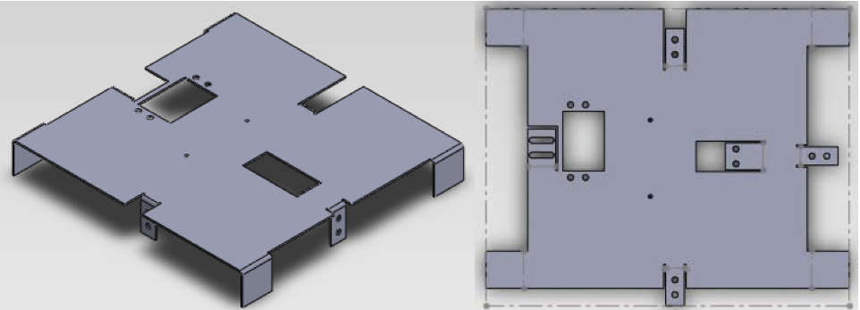
Base
The servo motors, gear stands, and batteries are mounted on the baseplate. The mounting points for the gear stands were designed such that the stands would lie flush with the ground. This, along with the 4 edge flanges, hold the base plate 1” off of the ground. The base plate is constructed of 0.030” aluminum sheet metal. The base plate was cut on the water‐jet machine because it would have been difficult to cut the tabs and punch the holes by hand. All of the mounting points are static with the exception of the slots for the vertical gear stand. This slot allows us to adjust the distance between the inner and outer gear.
Joints and Fasteners
The gears had a recessed cross onto which the servo horn was press‐fit. The servos were then epoxied to the gears. Many 8‐32 screws of varying lengths – specifically, five 2”, six 1⁄4”, three 1⁄2” – and two 1” 4‐40 screws were used to attach the stands to the base as well as the gears to the stands. Nuts were used to secure the screws in place, and washers and nylon spacers were included to reduce friction between components.
Power
The gears that move the Möbius strip are powered by two Gear Motor 4 (GM4) servos. These continuous rotation servos have an operating range of 3‐6 V, providing a speed of roughly 67‐77 RPM. As mentioned earlier, two of the gears are directly mounted onto the two servos. Because the servos are driving the same Möbius strip, it is important that they run at the same speed. To achieve this synchronization, they were attached in parallel to three AA batteries, which provided 4.5 V. Potentiometers were also attached to the motors so that fine‐tune adjustments of the speeds of the servos could be made but the potentiometers only functioned as on‐off switches. A laboratory DC Power Supply was used instead, so that the voltage to each of the motors could be controlled independently. The driving voltage was 2.9 volts.
Transmission
Gears
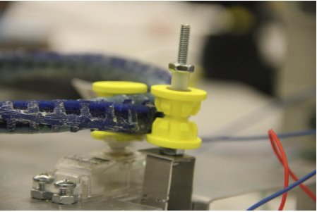
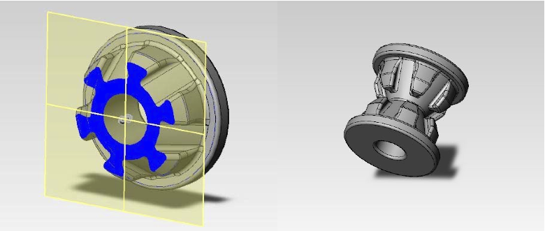
The gears were designed to accommodate the shape of the Möbius strip. Since the Möbius strip is designed similarly to a v‐belt to constrain the gears, the gears needed to be made with a groove along the toothed face. We designed them with a matching profile, but when we attempted to mate them in Solidworks they ended up having collision errors along every tooth. The only way to resolve this problem, while still retaining the ability to drive the Möbius gear, was to reshape the gears with a custom profile that is essentially the opposite of an involute.
The gears were printed on the FDM rapid prototyping machine. We were able to run the Möbius strip with far fewer gears than we originally expected (we printed 16) because they fit so well. A nylon spacer was placed down the shaft of the gear to reduce friction.
There was no slippage on the Möbius strip when the distance between the paired gear stands were correctly maintained. The passive planetary gears were removed from the final design to reduce friction in the movement of the Möbius strip.