Introduction
For this project, each team of four was tasked with designing an under-actuated mechanical hand using a series of three prototypes. After working on these prototypes for six weeks, all teams participated in a Final Competition where the performance of the hand was judged based on four criteria: Size, Mass, Dexterity, and Aesthetic Appeal.
To begin the project, we researched existing methods of underactuation to use in the fingers of our hand. We were able to use the knowledge gained from this research and apply it to our specific assignment in order to focus our design intent on the performance criteria necessary to do well in the Final Competition. Ultimately , we designed our finger using a four bar linkage as the base of the finger and much of our design was based on the work of Laliberte, Birglen, and Gosselin at Laval University.
Given that we had three opportunities to prototype our hand, our team's goal was was to start simple with the first prototype, and add complexity in later prototypes.
Design Overview
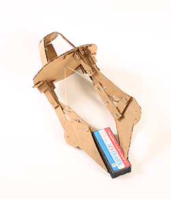
Before designing our first prototype, our team made a detailed sketch model using cardboard, hot glue, and string. This model, shown to the left, detailed our actuation, the configuration of our three fingers, and the shape of the base of our hand. The detail of this sketch model meant that we were able to focus on details early on in our process. We also realized, from this prototype, that the routing our cables from the fingers to the motor would be difficult, and require a pulley on the underside of our palm.
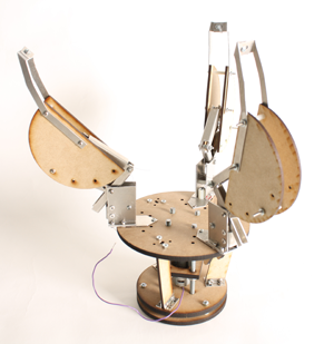
The first prototype was constrained to only include standard fasteners, sheet metal, and MDF(Medium Density Fiberboard). This prototype, shown in the image to the right, featured several adjustable components that allowed us to explore different finger configurations. The relative angles of the three fingers were adjustable so that our hand could grip items in spherical, cylindrical, and pinching configurations. Additionally, a knuckle was used to allow for the adjustability of the fingertip angle. Overall this first prototype worked very well and was able to grasp several different sized balls as well as an easter egg. We were very confident in the base of this first prototype but decided that the sturdiness and dexterity of the fingers could use some significant improvement.
When designing our second prototype, we kept the adjustability of the relative finger angles so that the hand could have three grip configurations. However, after using the first prototype to determine the ideal fingertip angle, we chose not to implement an adjustable fingertip angle in our second prototype. This prototype, shown to the bottom left, was constrained to be only made from standard fasteners,3D printed ABS, and Vitaflex. This second prototype successfully picked up the majority of the objects in the Final Competition, and overall we were very satisfied with it's performance. The major difficulties we encountered were with the routing of our cable between parts, thus in our final prototype we chose to focus on the interfaces between parts, especially the cable routing.
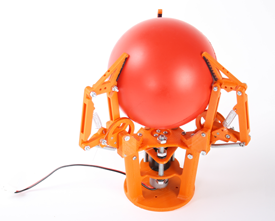
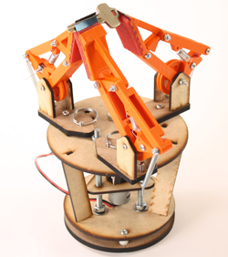
Our second prototype is shown to the left in it's spherical configuration, grasping a foam bowling ball. Overall, as a team we were able to continue to learn a significant amount from this second prototype including how to use 3D printing as a manufacturing technique and the strengths and weaknesses of using such a technique. Additionally, we were able to learn about polymers and molds and to add them to our knowledge base of fabrication techniques developed throughout this course.
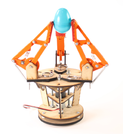
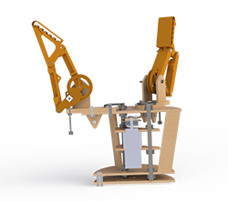
For our third and final prototype, we combined our sturdy MDF base design from our first prototype with our compact linkage design from our second prototype. With several minor improvements including improved cable routing, larger fingertips, and the addition of a fingernail, we were able to design our final prototype, shown to the right.
Structure
Fingers and Fingertips
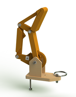
The fingers are made from a 3D printed ABS, formed into a four bar linkage transmission and tower which attaches to the palm at various angles. The finger subassembly can be seen to the left. The towers are laser cut medium density fiberboard structures which serve to lift the linkage off the palm and allow for different grip styles. The vertical support structures are fastened to the base with mortise and tenon joints, which gives the structure a high degree of strength while minimizing complexity.
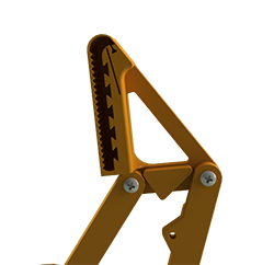
The linkages themselves were made from 3D printed ABS material. This allowed us to create compact linkages that included all the necessary stops and spring attachment points in a single fabrication step. The stops on the linkages are double sided protrusions which prevent each joint from closing past a certain angle. These stops ensure that the linkage rests in an open grasp position and prevent the linkage from entering a hyperextended position. The spring mounts are built into the lower and outer linkages. The spring that runs between these two points reduces the number of degrees of freedom of the finger until it comes into contact with an object, at which point the springs extend as the finger wraps around the object.
The fingertip is the primary grasping surface. A mold for Vitaflex, a compliant and slighlty sticky two part polymer, was built into the object facing surface. This fingerpad allows the finger to pick up oddly shaped objects in a variety of orientations by creating plenty of friction. However, the finger pad does not work well for picking up small objects. For this, a small piece of spring steel is fixted into the fingertip and protrudes out approximately 0.25". This fingernail is used to pick up smaller objects such as keys and pencils.
Base
The base of all of the hands are similar, consisting of a clock cage around a motor mount. The clock cage was formed by the palm plate, palm supports, a wrist platem and a mounting plate. The base of our final hand is shown to the left. The entire clock cage was designed two-dimensionally, and was laser cut out of 1/8” inch MDF. The palm plate connected the motor supports, the palm supports, and the fingers. The fingers are mounted to the palm using tower structures which allow the fingers to be rotated into the three different grasping positions. In our final design the MDF supports around the outside of the clock cage were use simply to add stability; most of the structure came from the motor mounts. The motor was mounted between three 1/4” all thread rods which ran from the palm plate to the wrist plate. Two MDF triangles with specific profile holes kept the motor constrained. Additionally, we used a two-plate system for attaching the hand to the arm. The wrist plate completed the clock cage and acted as a mounting point for the palm supports and motor mounts, but this plate was also bolted to a mounting plate which had the correct holes for mounting to the robotic arm. This allowed us to attach the mounting plate to the arm, and then the hand to the mounting plate, which was much easier to do at odd angles.
Power
The motion of the hand is powered by a Vigor Precision R280 Motor with a BO-P6 planetary gearbox. It has a 1.8kgf.cm output torque at the max efficiency speed of 36RPM. Because of its very high 120:1 gear ratio, it is very difficult to back drive. This is extremely useful for our application, because it means that when the hand has closed around an object, it cannot be opened without reversing the motor.
Transmission
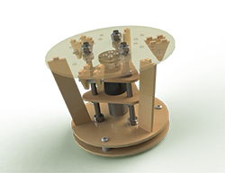
Connected to our motor, is our winch. When the winch turns it winds a cable which runs over a system of pulleys and connects to our linkages, actuating our fingers. An overview of our transmission is shown to the right.
Our winch is made of 1/8’’ thick mdf compressed between plates of sheet metal. The winch is attached to the hub by bolts which also attach the sheet metal plates to the mdf. Each of the three cables is wrapped around a bolt. When the bolts are screwed in tightly to the hub of the motor, the cables are compressed between the top plate of sheet metal and the mdf core. The cables are then wrapped around the mdf core as the winch is rotated by the motor.
Each cable runs over a pulley attached to the palm plate and through a bored out bolt. The bored out bolt attaches the tower to the palm plate, and is the point about which the towers rotate so that the routing of the cable is not affected when the tower’s position is adjusted. The cable is then routed around a cantilever pulley in the bottom bar of our four bar linkage, and attached to the back of the linkage. We attached the cables to the bottom linkage using two square nuts, which were fit into a square hole in the linkage. The inner of the two nuts was drilled through and not threaded so that turning the screw only tightened the outer nut. This method made it much easier and quicker to adjust the cables during the final competition.
Attaching the cable to the back of the bottom linkage meant that tensioning our cable caused a twisting motion instead of a linear pulling motion. This allows the inner bar of our linkages to stay stationary when it comes into contact with an object, while causing the finger tip wrap around the object the hand is grasping. Mechanical stops to prevent hyperextension were built into the linkages, as well as holes for the attachment of springs. The springs provide the restoring force in our system, returning our fingers to an open position when the cable is not tensioned.
Fabrication
As mentioned in the design overview, each of the three prototypes had certain material constraints. The first prototype was limited to only include standard fasteners, sheet metal, and MDF(Medium Density Fiberboard). The second prototype was constrained to standard fasteners, 3D printed ABS , and a two part compliant polymer. Finally, for the third prototype we could use all the previous materials (fasteners, sheet metal, MDF, ABS, and compliant polymer) but in much smaller quantities than our previous two hands.
We chose to 3D print our linkages and fingertips using ABS because the built in stops and molds made them difficult to use other manufacturing techniques. Additionally, for this prototype we chose not to use sheet metal because during our first prototype we found that we were not able to bend the sheet metal very accurately. Having used nearly all our allocated 7 in3 of ABS in the fingers, we chose to make the base entirely out of fasteners and laser cut MDF. Thus, we only used three manufacturing techniques: laser cutting MDF, 3D printing ABS, and mold pouring.
Results
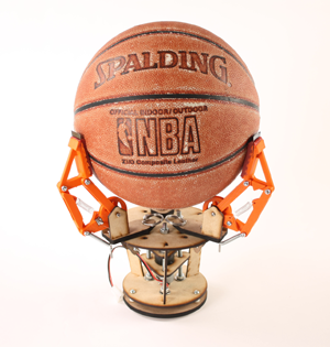
Our hand performed quite well in the Final Competition: it won the dexterity and size categories, tied in the weight category, and came in first overall. Our hand was able to pick up a large variety of objects: everything from 5/16” metal ball bearings to basketballs and ice cubes. The fingernails proved to be critical to the hand’s performance, allowing us to pick up arbitrarily small objects, including a grain of rice, and slippery objects such as ice cubes. The large compliant polymer pads helped us grasp things much larger than the fingers themselves, letting us palm the basketball even though the fingers could not reach the midway point.
Our hand was successfully able to grasp, raise, twist and replace: a 5/16” ball bearing , a basketball, a key, a grain of rice, an ice cube, a paperback book, a 5 pound dumbbell and an easter egg
Future Improvements
While the hand did well, it was by no means perfect. Were the hand to be used as a general purpose robotic gripper, it would need to be able to reorient the fingers without a human interaction. Furthermore, a stronger actuator would be required to lift objects onto the palm and move objects with the fingers alone. This also means that the linkages and support structure would need to be redesigned for greater stability. Our hand is explicitly designed for high symmetry objects and it fares poorly for oddly shaped things like hand drills. A pulley tree system would allow the fingers to tighten asymmetrically, meaning that the fingers could wrap more effectively around complicated forms. Our hand was unable to pick up and reorient weights heavier than 5 pounds because the long clock cage gave the weight a huge lever on the arm actuator, which quickly hit its torque limit. While this could be fixed by used a stronger arm, a smaller clock cage would also reduce the stresses in the structure of the hand.