Executive Summary
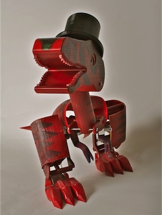
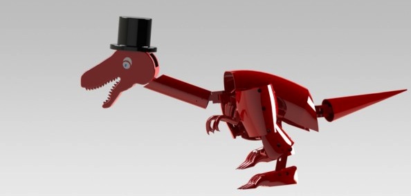
As the final project for Introduction to Mechanical Prototyping Fall 2011, we were charged with designing and prototyping a crawler that utilized sheet metal, 3D printing, polymers, and finishing techniques. This group decided to take on the task of building a biped crawler with center of mass shifts for balance. We drew inspiration for this design from the velociraptor, a carnivorous dinosaur commonly featured in popular culture. Our velociraptor, named Flynn, has a custom-designed leg mechanism that uses both 3D printed and sheet metal linkages. The head and the tail were rapid prototyped in order to achieve realistic surfacing. They were mechanically linked to the legs in such a way that a side-swinging motion with each step would shift the center of mass onto the foot that remained on the ground, thus allowing Flynn to stay balanced while walking forward. For integrating elastomers, we decided to form the arms through silicone molding. After all, no dinosaur is complete without its little, primarily nonfunctional, arms. Finally, we finished all the surfaces with glossy, brick red spray paint and black stripes to create a semi-realistic, yet whimsical, appearance.
Inspiration
One of the concepts that inspired our velociraptor design was the Titrus III robot developed at the Tokyo Institute of Technology. Featured in a YouTube video, the dinosaur-like biped robot moves its head and tail laterally to shift its center of mass. This allows it to balance on one leg while moving the other leg forward. The batteries are housed in the head and tail, which helps counteract the mass of the body.
The Titrus uses 8 servo motors, individually controlled by a microcontroller. Our challenge was to replicate the motion of the Titrus, but using one continuous-motion motor. We also wanted to have a more dinosaur-like gait, posture, and appearance.
Surfacing
Legs and Feet
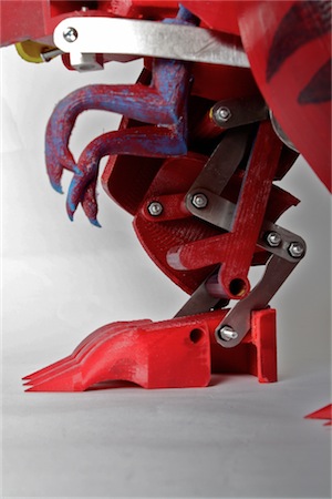
Flynn’s legs and feet were designed for both functionality as well as style; one of our goals was to make a realistic-looking velociraptor. The surfacing for the legs was accomplished after the main leg mechanism had been designed. Due to the complexity of the legs, it made most sense to create leg panels instead of a whole, continuous shell. From a side view, each leg can be described as having three parts: the top two were made out of RP and had surface extensions to make the legs look muscular and the bottom one was made of sheet metal. The sheet metal the design called for proved to be unavailable for our construction, and the sheet metal we substituted was too thin and resulted in a wobbly leg assembly that could not properly support Flynn. Looking back, we also would make changes to the structure of the feet. We were happy with the realistic appearance of the feet, but in terms of functionality, they were not wide enough to accommodate the sizes of both the body and the legs. As seen in the Titus III dinosaur, the feet needed to extend further underneath the body so that there was only an inch or so of clearance between the two feet. This ensures that the center of mass doesn’t have to shift drastically in one direction, whereas Flynn would have had to shift his center at least four or five inches in order to be positioned enough over one foot to maintain balance.
Head and Tail
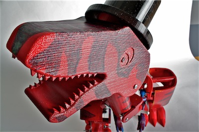
In order for Flynn to be able to balance while walking, we designed a mechanism where the head and tail shifted as he walked. The head and tail moved such that they were over the leg that was on the floor, therefore shifting the center of mass to be over the leg on the floor, giving Flynn better balance. Both the head and tail housed two batteries to give them more mass. The head was also designed to be adjustable so that the neck could be rotated to move the head further from or closer to the body. This allowed for us to adjust where the mass of the head was located, giving us further control over Flynn’s center of mass. After building Flynn, we found that the head was too heavy with the batteries in it, and so the batteries in the final design were located in the tail and in the back of the body.
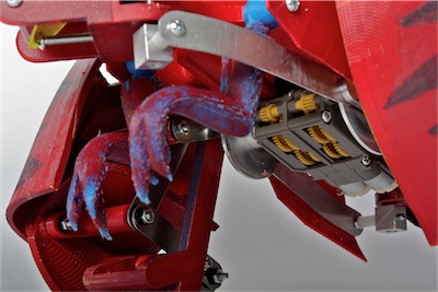
Power Source
We powered our crawler using a Tamiya twin motor gearbox, powered by 4 AA batteries. The motors needed to run at equivalent speeds in order for each leg to move at the same speed, so we modified the gearbox with an extra set of gears that interfaced between each of the twin motors, ensuring synchronous motion. Because our velociraptor was so large, we set up our motor so that it was running at the lowest speed and highest torque possible in an attempt to give it enough torque to walk.
Transmission
Legs: Gait and Assembly
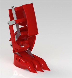
Flynn’s legs were designed using a linkage system that centered around two design objectives. First, the legs should have an organic walking motion, meant to imitate the gait of a velociraptor. Inspiration for our particular motion was drawn primarily from previous collaborative work between paleontologists and animators, especially that featured in the Jurassic Park movie franchise. Secondly, the feet needed to remain parallel to the ground at all times. If the feet were able to pivot, Flynn’s legs and body would also be able to rotate about the point where they connected to the feet, causing him to constantly be falling forward or backward. This would have resulted in a highly unstable system. The linkage system needed to allow for natural motion was complex on its own, but a parallel linkage system was also required to force the feet to remain parallel to the ground and the velociraptor. This secondary linkage system more than doubled the number of required parts and resulted in a highly complex system that required innovative design of several components to avoid interference. The legs were designed with components to be either printed on a rapid prototyping machine or, if three dimensional design was unimportant, to be produced using sheet metal. It was meant to be constructed using 0.10 inch thick metal, but the actual sheet metal we had available was 0.03 inches. That led to a loss in structural integrity, as it became difficult to space components appropriately. Some of that structural integrity loss led to slop in the linkages, and it became almost impossible to keep the feet parallel to the ground.
The system was designed such that pivots points would be provided by bolts that the components could rotate around. Unfortunately, many of these pivot points were in largely inaccessible areas, thus making construction extremely problematic.
Head and Tail: Actuation, Timing, and Balance Control
The head and tail of the Titrus robot each had two individually-controlled servo motors to control their position and make sure the head and tail were in the correct location at the correct time. Our 1-motor technique required that we do all of the timing and actuation mechanically from the same motor that drives both legs.
To do this, we used pin joints to attach the neck and tail to the body. This gave them one degree of freedom so they could easily move from side to side. The actuation was done using sheet-metal push-rods that were driven by the hubs attached to the gearbox. These act similarly to the connecting rods that connect pistons to the crankshaft in an internal combustion engine, converting rotary motion into linear motion.
Where the push-rods connect to the neck and tail, we needed a joint with two degrees of freedom. Rather than using ball-joints like the Titrus, we machined our own two-axis pin-joints.
Timing was also a challenge since the legs needed to be out of phase, but the head and tail needed to move in phase with each other. We were able to achieve this by designing and machining a timing adapter that attached to one of our hubs that allowed the push-rod for the head to be mounted 180° out of phase from the part that drives the leg.
Reflection and Future Improvements
Given that our Flynn didn’t perform as we hoped, there are quite a few things we would do differently if we went back and did it again.
Several problems became apparent quite quickly during assembly. One was that we had done a very poor job in the “design for easy assembly” department. Each of the legs took several hours to assemble and often two or three people were needed since one person had to hold the parts in place while one or two held the washers, nuts, and bolts in place. Once it was assembled, most of the bolts required three hands for adjusting them and some were impossible to reach since they were obscured by other parts, which also made it difficult to trim the bolts so that they didn’t cause interferences within the leg linkages.
One solution for the problem may be to tap threads into the RP material and screw the bolts directly into the plastic. Also, it may make sense to have removable body panels so we can assemble and test the mechanical parts without the interference of the stylistic parts.
Once assembled, it became clear that the legs were much less stable than we had anticipated. Due to slop in the linkages, the feet were not actually constrained to be parallel to the ground. In the future, it would make sense to prototype any unproven linkages using a sketch-model. This would give us intuition on the real-world performance rather than relying on the idealized conditions of a SolidWorks simulation.
Flynn also proved to be quite heavy once it was assembled, and quite large. Although the size made it closer to the size of an actual velociraptor, which was something we liked, it would have been much easier to move, and possibly more stable, if it had been smaller.