Introduction
The inspiration for this project came from Dr. Aaron Hoover’s original Möbius Gear design. While we used the same concept and general geometry, we have made a number of improvements including more selective compliance and adjusting the width and diameter of the Möbius gear. These changes eliminated many of the problems observed with the original model by keeping all gears sufficiently aligned with each other.
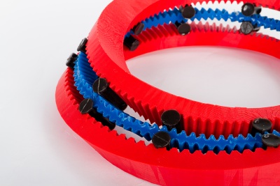
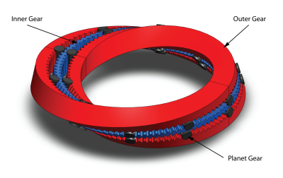
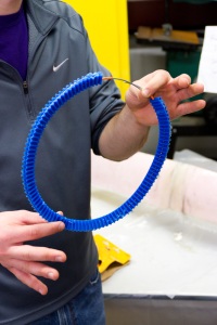
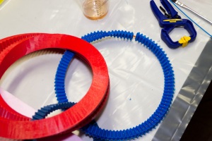
The Möbius Gear has three major components, which we have designated the inner gear, the outer gear, and the planet gears. The outer gear is rigid and stationary and provides the structure for the moving components. The inner gear is a semi-compliant Möbius strip with teeth on its one face. It is made from silicone molded over a rigid metal wire, which allows it to keep its neutral axis ciruclar but still twist as it rotates through the outer gear. The planet gears are what provide the interface between the inner and outer gears and make sure that the inner gear twists and rolls correctly along the outer gear.
Major Design Decisions
Our most crucial design insight occurred when we realized the inner gear needed to be rigidly fixed along its neutral axis. If this was not the case, pulling on the inner gear caused the planets and the inner gear to begin slipping out of the outer gear. Based on our experience from several iterations, we decided that the best way to avoid this would be to embed a metal wire inside the inner gear. We decided to use a relatively soft 1/32" galvanized steel wire, which was easy to bend into the correct size circle. This prevented any kind of permanent spring loading on the strip.
Since the inner gear still needs to be able to twist, though, instead of embedding the wire directly into the silicone, we embedded a small plastic tube first. The wire, pre-formed into a circular shape, was then inserted into the inner gear. We found that this method significantly improved functionality by reducing friction, eliminating lateral gear slippage, keeping the inner gear face sufficiently parallel to the matching outer gear face. One remaining problem is joining the ends of the wire together. In our case, they are not joined, but offset from the point where the inner gear is joined together.
Another significant improvement was increasing the diameter of the inner gear to 8". We reasoned that the critical determining factor for how well the gears operate is the amount of tooth “warping" that occurs when a constant pitch is used. The tooth warping, basically tapering, narrowing, or widening depending on the position along the outer gear, is characterized by the ratio of tooth size to gear diameter. In order for the teeth to be less warped, the diameter must be increased or the tooth size must be decreased. Since we opted to fabricate our parts using an FDM machine with tolerances of +/- 0.01", we determined that using smaller teeth was not an option. Thus, we increased the gear diameter to 8".
Other minor design decisions we implemented were focused around enhancing planet gear performance. For instance, we increased the width of the inner, outer, and planet gears (although our final implementation has an inner gear that is narrower than the outer gear), which prevented the planets from slipping out during operation. Further, we added retaining features along the outside of each planet which kept them in line with the inner and outer gears and prevented them from slipping sideways. Finally, we modified the tooth shape to be a trapezoidal cut instead of triangular. While the tooth shape on the inner and outer gears changes depending on the twist angle, the cut in between teeth is always the same. This means that no matter the position, the teeth on the planet gears can always engage with their counterparts.
Fabrication
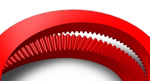
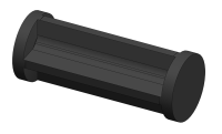
The first element of the system we created was the rigid outer gear. This part was produced with the rapid prototype technique of fused deposition modeling, an additive 3D printing method that uses heated ABS plastic to create parts layer by layer. Printing the outer structure in one piece took a number of days at the highest resolution setting, but it was the most reliable and cost effective method for creating a piece of its precision and complexity. The final product was rigid, gorgeous, and as precise as needed. With the outer gear printed, we could begin to produce and integrate the other components of our design.
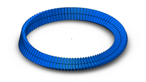
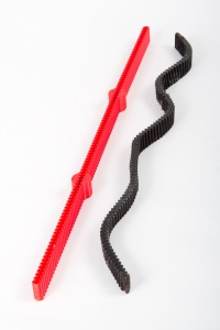
The next part we focused on creating was the compliant inner gear. After a number of material and design revisions, the final inner gear was molded out of MoldStar 30, a soft yet durable silicone from Reynolds’ catalog. The inner gear was molded as a straight rack gear, removed from it mold, and manually twisted into a Mobius gear. In order to give the gear structure along its neutral axis, the inner gear was molded with a hollow plastic tube traveling through the middle of the silicone strip. When the gear was removed and shaped into a Mobius structure, we fed a pre-bent galvanized steel wire through the hollow tube, fixing the structure as a ring around which the silicone teeth could bend. The piece was then placed back into the mold and joined together into the final Mobius structure by pouring the last tooth with the same silicone mix.
The inner gear was produced using 3D-printed molds, which, just like the inner gear itself, had undergone a series of revisions to make them reusable yet breakable if the compliant material was difficult to remove safely. When used in conjunction with shellac and Mold Release, the bendable gear mold allowed us to safely and easily remove the silicone gear. Given the length of the gear and the size limitations of the 3D printer, the mold was produced in three pieces. The mold was designed to make the gear initially linear, so that all of the teeth had the same shape and were not biased by the curvature of the final Mobius shape.
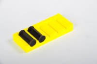
With the outer and inner gears created, the next step was to create the planetary gears that would ultimately keep the inner gear on track. As with the inner gear, we created reusable 3D printed molds for the planetary gears. For the sake of precision and easy removal of the gears, the molds were designed as two parts with locating features that locked into each other. These molds fit together snugly and were open at the top to allow for easy and quick pouring. In order to ensure that there were no bubbles present in any of the gears during the molding phase, we put the urethane mix in a vacuum before pouring the individual gears. The final product was a stiff, yet bendable enough, planetary gear that interfaced with both the inner and outer gears well.
Potential Improvements
Despite the improvements we made on the design of the Möbius gear, there are still several issues with the design and fabrication that should be addressed in further iterations. With the fabrication, the main issue is with properly joining the Möbius gear. In our current Möbius gear, the internal metal wire is not joined, which leaves a weak point in the structure of the gear. Our solution of rotating the metal wire within the gear so that the break in the wire and the weak bond in the silicone do not overlap is a quick fix to the problem.
Ideally, the metal wire would be joined together to fix any extensibility of the silicone over the tubing. Possible solutions include clamping the wire together, welding it, or using a thinner wire so that the offset of overlapping the wires is not as significant. The main difficulty in any of these solutions is that the workspace is so small, since there is essentially the span of one tooth on the Möbius gear to connect the wire together.
Another problem with our fabrication was that the Möbius gear was not properly bonded to itself because the joining tooth was poured after the cure time for the rest of the gear. Even though silicone is best at bonding with silicone, the bond between uncured silicone to cured silicone is not as strong as uncured to uncured. When we first joined the Möbius gear together, the gear broke at the joint within a couple of minutes of use. To fix this in the future, the silicone needs to be removed from the mold before the cure time. This adds another level of difficulty in properly fabricating the Möbius gear, because whatever joining method used on the wire, as well as pouring the joining tooth, must be done between the de-mold time and the cure time.
The main problem with our current design is that the outer FDM gear flexes under use; there are no constraining features to make sure that the outer gear does not flex as the planetary gears mesh teeth. In our current version, this flex causes the planetary gears to skip. Adding features that constrain the two sides of the outer gear together would solve this issue, either by adding bars across the two sides, or by mounting the outer gear on to a base that constrains the sides relative to each other. While constraining the two sides would induce more friction into moving the Möbius gear, the rigidity would increase the consistency in moving the Möbius gear. We believe that this consistency is the key aspect in creating a Möbius gear that can reliably run by being powered from motors.