Introduction
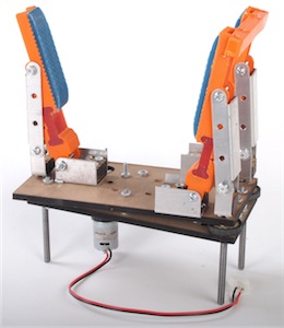
For the final six weeks of the Introduction to Mechanical Prototyping class, we undertook the assignment of building three prototypes of an underactuated hand. An underactuated hand has more degrees of freedom that the number of actuators. For our version of an underactuated hand, one motor runs a belt that actuates a set of threaded rods up and down. This motion causes the fingers to close. They are designed in such a way that when the fingers encounter an object, the fingers curl inwards.
We built skills in prototyping with many different types of materials in each of our prototypes: first, using sheet metal and MDF (of thicknesses 1/8in and 1/4in;); second, using 3D printed thermoplastic; and third, using all materials used in the previous two tasks.
The final design had the challenge of creating a hand that could compete in the fields of dexterity, aesthetic appeal, and relative strength. All teams were afforded a $25 McMaster-Carr order, one 8x8in 1/4in thickness MDF sheet, one 8x8in 1/8in thickness MDF sheet, one 8x8 sheet metal, and 7 cu.in. of 3D-printed thermoplastic.
Design Overview
Our main goal throughout the project was to investigate the use of linear motion to actuate a linkage-based finger design. We employed various techniques for our previous two designs and combined the lessons we learned to create our third and final prototype.
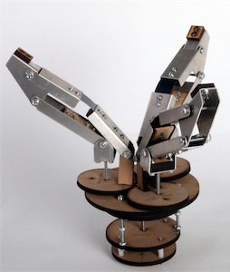
Our first prototype was constructed from sheet metal and MDF. The fingers were five-bar linkages that were translated up and down by lead screws that raised a platform at the bottom of each finger. From this prototype, we decided that linkages produced desirable results and therefore kept this theme across all following designs. Additionally, the use of lead screws to drive the motion of our fingers ensured that there would be no backdrive in our transmission system. We did not like, however, the raising platform as it placed a great deal of load on the motor, rendering the motion extremely slow.
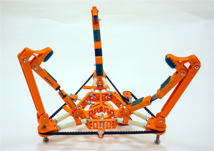
Our second prototype was made from 3D-printed thermoplastic along with polymers Vytaflex-10 and PMC-780. In this prototype, we investigated the use of belts as a form of transmission for all three fingers. We learned a lot about stand-offs (connections for each finger to the base) in this prototype which proved to be extremely useful for our final prototype. It was quite slow so we made a note to choose a higher screw pitch to make the motion faster. The second prototype also brought into sharp focus the drawbacks of our five-bar finger linkages. We decided to instead have a four-bar linkage finger with one flexible joint. This prototype also inspired our beefier final design.
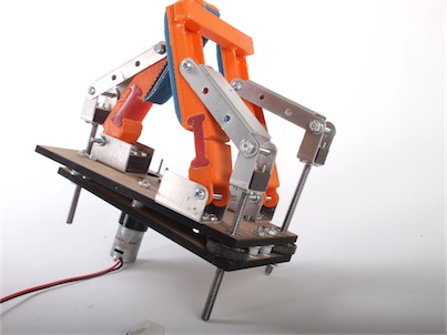
Our final design incorporated MDF, RP thermoplastic, and sheet metal (due to the low supply of RP thermoplastic). Bearing the lessons learned from previous prototypes in mind, we created an extremely robust, rigid hand that was able to pick up a variety of objects.
Structure
The two main structures of our hand are the fingers and the base. Each of the fingers is attached at two points to the base. One of these points is a pivot that is fixed to a sheet metal bracket which is bolted to the base. The other point is another pivot which rides on top of a lead screw that moves up and down, which actuates the finger.
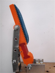
The finger is similar to a four bar linkage when the motor is stationary. The ABS part of the finger contains two bars and three pivots. One of the pivots is connected to the third bar, which is the sheet metal back of the finger. On the opposite extreme of the finger is a pivot that connects to the bracket bolted to the base. The third pivot lies midway between the two and is a polymer flexure joint. The virtual fourth bar lies between the pivot on the lead screw and the pivot that is bolted to the base. This means that when the motor is at rest, the finger can still move, and is therefore underactuated.
The base is made of two parallel plates. The upper plate serves mainly as a support for bushings and screws. The upper plate is supported by several pylons made of spacers and washers which are held on with bolts that go through both plates. These pylons hold the two plates slightly further apart than the height of the pulleys 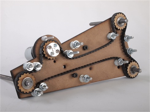 and a few washers, which allows the pulleys to rotate with low friction against the top and bottom. The bottom plate has matching holes for the bushings and screws, as well as the motor mount. The motor was supposed to be constrained by a special support, but friction was enough to hold it in during testing, so we did not use the support.
Inside the two plates, there is a system with multiple pulleys driven by a pulley connected to the motor, which runs a 28” XL timing belt. There are two types of pulleys: drive pulleys, which have teeth and interface with the toothed side of the belt to drive the belt or the leadscrews, and roller pulleys, which are there to change the angle of the belt going into or out of the belt.
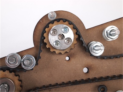
The lead screws are also constrained by the base. They are screwed into a nut embedded in a pulley which floats between a bushing in the top of the base and a washer that helps prevent the pulley from rubbing on the bottom plate at the bottom of the base. Originally two precision bushings were meant to press into the top and bottom of the plates to guide the lead screw. Unfortunately, the combination of a very tight tolerance on the bushing, (+.00075” on radially, or .0015 on the diameter between the rod and the bushing) and the low precision where the holes were drilled by the laser cutter caused the rod to bend and jam up because they were not concentric.
Transmission
Transmission of our final prototype was achieved by using a belt, a set of belt gears, and a set of lead screws. The motor is securely attached to the base using its guide screws and recessing its unique profile in the MDF base. The hub of the motor was attached to a belt-driving gear made from MDF that interfaced perfectly with the XL #4 timing belt from McMaster-Carr. Each finger has its own gear that is driven by the belt. The gears contain captivate-nuts which drive a 1/4-16 Acme leadscrew up and down as the gears rotate. The top of each leadscrew is securely attached to a small box at the back base of the finger.
The fingers are a simple four bar linkage, where one of the joints is made of PMC-780 polymer. The finger motion was created simply by pushing on the back linkage. Since the front base linkage is a pivot whose vertical position is fixed, the tip of the finger would bend inwards. Lower the threaded rod would spread the fingers.
Power
All prototypes of our underactuated hand are powered by a BO-P6 with R280 motor found under the planetary gearbox collection by Vigor Precision LTD. The gear ratio of this motor is 1:120, providing a geared down speed and higher torque output by a factor of 120. It provides a continuous rotary motion with an output torque of 2.0 to 15.0 Kgf-cm. The BO-P6 motor is 66g and operates in a voltage range of 3.0 to 24.0 V DC. We used it at 6V so that the torque would be high enough to apply the force required to pick of a reasonable range of objects. Without loading, it spins at 60 to 200 rpm. A motor hub and gears were attached to the shaft, which drove the belt that gave our fingers motion.
Fabrication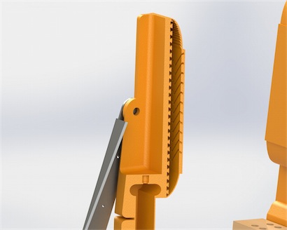
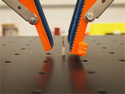
Fabrication of our underactuated required a fair bit of teamwork. The easier and most pain-free part of building was definitely the construction of the finger pieces. Unfortunately, the polymers were poured in the reverse (i.e. VitaFlex was where PMC-780 should have been and vise-verca). Fortunately, we were able to scrape out the Vita-Flex from the joint and were able to successfully repore the PMC-780. We were not able to remove the PMC-780 from the finger tips, so we were not able to grip things as well. Despite this, our grip was still strong and were were able to pick up surprisingly small objects.
The sheet metal parts were quite easy to cut and bend was we had ensured that the dimensions for this section coincided well with the restrictions of the finger-press. MDF pieces were uses as support between the sheet metal parts and were cut with the laser cutter.
By far the most complex part to construct was the base/belt driving system. It firstly took quite a while to ensure that the tension on the belt was sufficient. Seconly, it took two people to coordinate putting the top plate onto the lower base plate as there were so many accessory screws. We had expected this to be the case, so we budgeted our time effectively.
Attaching the fingers to the threaded rods was painless. The final part that we added to our assembly was an RP part between two adjacent fingers. Since keeping the two fingers initially separate made them easier to attach to the base, so we decided to add the bar via epoxy (as opposed to via a merge). We salvaged this piece from our second prototype to save on material.
Future Improvements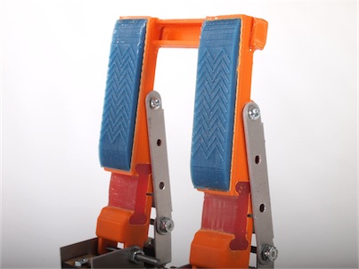
There are various ways that this hand could be improved with more iterations. The main sticking point that limited our abilities was the leadscrews not having enough torque to create a firmer grasp. Poor belt tension and friction on the lead screw led to this.
The first improvement would be to ensure that the holes for the bushings are drilled concentric. To do this, we would laser pilot holes for the pylons and leadscrews plate to locate the approximate position. Then we would clamp the plates together and drill all the holes, ensuring that they are concentric. This would allow us to use bushings to reduce wear between the leadscrew and MDF bases, and lower the friction because the MDF on steel contact would be replaced with steel on aluminum. Having the two bearings on the top and bottom would keep the leadscrews perpendicular to the bases. This would reduce friction because with only one bushing, the belt torques the leadscrew , which causes the belt and pulley to rub against the base.
One area of future study could be to use separate belts for each leadscrew, or to add spring loaded idlers. Our design had low tension than desired, which we compensated for by having a lot of teeth engaged with the belt, and with a roller to force the belt onto the teeth of the pulleys. If each leadscrew had a separate belt, each one could have a single adjustable roller for adjusting tension. This would require either separate planes for the pulleys or another gear train, but it would be possible and even easy to do this.
Another improvement would be to create adjustable grasps. This would be done by making the front mounting bracket for the fingers adjustable. This would require that the base increase in size, but it would not require a change of belt length, or an adjustable base.
The final improvement that would definitely have to be in the next iteration is an adjustable and better designed cross bar for the two fingered side. It would have to flex to accommodate different grips, or at least rotate in some way to get both pinch and cylindrical grasps.
Overall the design of the grasp is robust enough to pick up some interesting objects, from crimps to a large ~6” ball, to screwdrivers. It is elegant and simple, but the abilities were restricted by problems in transmission.