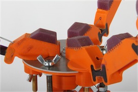
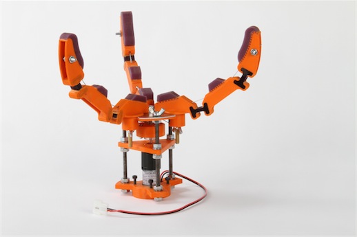
 Introduction
The final project in our Mechanical Prototyping class was the design and manufacture of an underactuated hand. The hand was to be designed to be attached to a robotic arm and complete a series of lifting challenges: a series of barbells with varying weights, a series of spheres with varying radii, a key, a bar of soap, and a plastic easter egg, a drill, an ice cube, and various other items. Because of the wide variety of objects our hand needed to grasp, it was important that our hand would be able to conform to a wide variety of shapes, but not have so many degrees of freedom that it cannot hold its grasp.
The hand used in competition was the last of three prototypes. The first prototype was constructed with medium density fiberboard (MDF) and aluminum sheet metal. The second prototype was built using 3D printed Acrylonitrile butadiene styrene (ABS). The material constraints on this hand included all previously used materials; however, our final prototype is built primarily out of ABS and consumer off-the-shelf parts (COTS parts).
Design Overview
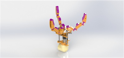
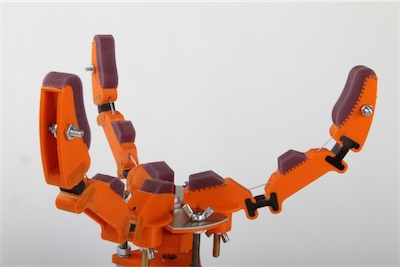
Our main goals for our final prototype were fourfold: multi-configurability, simplicity, constructability, and lightness. Multiconfigurability was achieved on three distinct levels: finger underactuation, fingertip conformance, and finger repositioning. The phalanges of each finger are controlled with the tension from a single length of steel cable, but because the phalanges are attached with polymer joints, the fingers will naturally try to return to an open state. Because the innermost joint is weaker than the outermost joint, the whole finger will naturally bend inward as a whole unit until it contacts a surface. when the first phalanx stops moving, the cable continues to pull, and the second phalanx will actuate inward until it too contacts the inner surface.
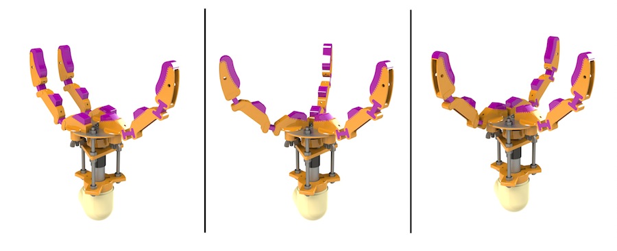
The phalanges on different fingers may arrange in different positions from one another, however, if one entire finger remains fully motionless, the other fingers will also stop.
In addition, each of the fingers uses a thin layer of soft polymer as finger pads. These pads conform to the shape of the objects they come into contact with, providing greater surface area. This gives the finger a solid grip on a wide variety of surfaces. Finally, each finger can be manually rotated into 12 discrete positions, each 30 degrees apart. This allows for many distinct configurations, each suited for picking up different classes of objects. This level of adaptability ensures that the same hand which can pick up a large sphere can also pick a small key.
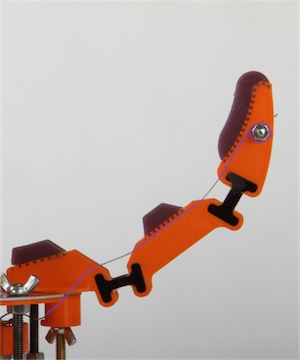
One significant improvement made over the different prototypes was simplicity in the cable path. While originally, the cable was wound around many pulleys, the final cable path is direct and has little friction. We copied the general routing path from the Harvard hand, and the result was much smoother actuation with much lower forces.
Furthermore, our design was easily and quickly constructible. Once the parts are printed and waterjet cut, and the polymers are poured and have set, the base can be assembled in about 15 minutes using only a screwdriver and a pair of pliers, and the fingers can be attached in under a minute. After the cables are routed through the fingers, the cable length can be adjusted at the fingertip using just needle-nose pliers. Finally, reconfiguring the fingers can be done without removing the hand from the arm very quickly without using tools. Since the final competition was timed, quick reconfigurability is important to our overall success.
Structure
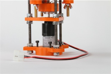
The base of our hand screws into the robotic arm, houses the motor and winch, and holds the fingers in place. The fingers hold their polymer finger pads and house the wire running through them. The fingers of the hand are similar to human fingers – they are constructed of several phalanges connected by joints with a tendon running through them to move the fingers. The joint is made of a flexible polymer which bends, but tries to open the fingers back up when the cable tension is released. Each finger phalanx has a finger pad made of a cushioning, soft polymer. This finger pad acts like the flesh in human fingers, making it easier to grip objects.
The base consists of three parallel base plates. The top plate holds the fingers in place, the middle plate mounts the motor, and the bottom plate attaches the hand to the robotic arm. These baseplates are connected by three threaded steel rods and secured by nuts. These threaded rods created a rigid support and allowed us to make a large, strong hand with minimal material and weight. The top plate was reused from that last prototype, but because we were worried about its structural integrity, we waterjet cut an identical sheet metal top plate to reinforce it.
Power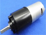
The power for our hand is provided by a BO-P6 with R280 motor from Vigor Precision LTD. This motor is capable of generating 1.8 kg-cm of torque at 42 revolutions per minute - just the speed and torque we need. Using this motor helps us keep our design small, compact and light. Another advantage of this motor is that it cannot be back-driven. This will stop the fingers from opening when we don’t want them to. The motor is mounted semi-permanently to the middle base platform.
Transmission
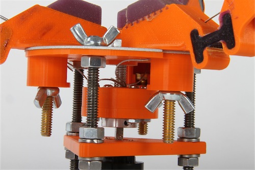
The spool is a modified 1/4-20 bolt with a slot cut into the end opposite the head which is fastened to an embedded nut. The small diameter of the bolt provides us with a high amount of torque and control when operating the hand. One end of each of the cables is placed inside of this slot and clamped between the interior of the slot and a plate that secures the embedded nut. On the opposite end, the cable is secured to the finger tips by similarly modified bolts. These bolts have holes which the cables are threaded through. The cables can be clamped to the bolts by tightening nuts against them.
When the three cables are pulled, the fingers close toward each other. Depending on how the fingers are rotated, the fingers can be closed around differently shaped objects. Due to symmetrical holes and features in the phalanges, both the middle and end phalanx of each finger close at the same time. In future iterations, we wish to have the middle phalanx close first to allow the hand to pick up smaller objects and have a firmer grip on larger objects.
Fabrication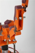
By 3D-printing the majority of our hand with plastic, our fabrication process was relatively simple. The process of 3D-printing allowed us to create custom, complex geometries and aesthetically pleasing features in our parts. This additive manufacturing process allowed us to create custom parts, exact copies from our computer designs, with little fabrication involved. Not only did this reduce the labor required in manufacturing the hand, it greatly decreased the chances of error and incorrect machining. 3D-printing our hand made it possible to create the interlocking base joints of the fingers allowing for multiple configurations. Furthermore, molds for the polymer finger pads and phalanx joints could be built right into the printed plastic part. The second part of fabrication involved pouring the two different polymers into the polymer molds built into the fingers. Once the polymers had cured, the edges of the molds were sanded down and broken off, exposing the polymer joint and finger pad features. The final fabrication process involved having a second copy of our top base plate water-jet cut out of sheet metal to reinforce it. The fingers and bases were then attached and secured with nuts and bolts.
 Future Improvements
There are many improvements we could make upon our design. The primary issue with our design was proper cable tensioning. It was very difficult for us to correctly tension each of the fingers so they would be balanced. This greatly affected our ability to pinch objects because the fingers would not all come together in a synchronized movement. This also made it dificult to pick up small objects because one finger would push the object away before the others would come into contact. To fix this problem we could either develop a method or design a mechanism to allow us to correctly tension the cables.
Another improvement to our design would be the addition of finger nails. A problem that we hot fixed the day before competition was our inability to get underneath flat objects like the CD and key. Our fix was adding small finger nails made from spring steel sheets. This worked to some degree, but it would be better to design a more thoughtout mechanism.
Lastly, we would probably like to use a different material for the cable. Since the diameter of our spool was so small, the steel cable would deform a lot and made operating inconsistent. If we used a more flexible material the cable would not deform, and it would be easier to thread through the fingers. On the other hand, a flexible material of that diameter would probably not be as strong as steel cable.
