Introduction
The purpose of this project was to build an underactuated hand through an iterative design process utilizing a variety of materials and fabrication techniques. For the final design, we were limited to the use of seven cubic inches of fused deposition modeling (FDM) ABS plastic, an eight by eight inch square of eighth inch thick medium density fiberboard (MDF), an eight by eight inch square of quarter inch thick MDF, and a ten by ten inch square piece of alumnium sheet metal. We were also allowed to purchase up to $25 of fasteners from McMaster Carr, a mechanical component supplier.
Design Overview
We aimed to design a prototype that was both functional and easy to assemble. We wanted the hand to be able to pick up a variety of objects of different shapes and sizes. Additionally, we aimed to explore a number of different design possibilities before settling on a final design.
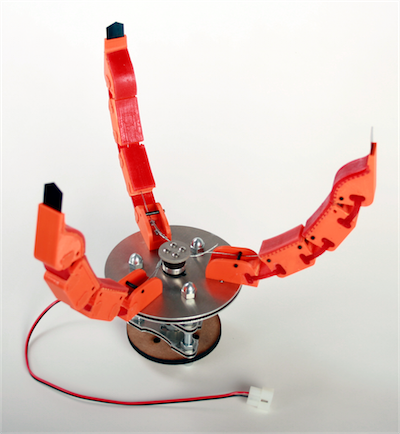
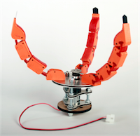
Our final prototype meets our design goals fairly well - our hand is easy to assemble and is able to easily grasp a number of objects. The majority of components are fabricated using laser cutting or 3D printing, minimizing manual fabrication requirements. The final hand is compact and smoothly functional. Throughout the design process, we tested multiple novel design concepts and incorporated the knowledge acquired from the tests to create the final hand.
Structure
Palm and Motor Mount
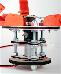
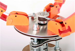
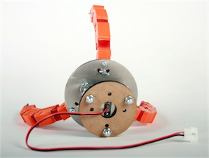
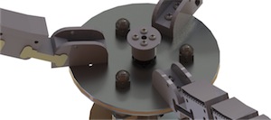
Sheet metal and MDF ‘sandwiches’ are cut with a variety of profiles to support the fingers, house the motor, and provide a mounting plate for interfacing with the robot arm. They are securely held in position by bolts and three threaded rods. The top ‘sandwich’ is a large disk with a hole cut into the profile of the motor in the center, which keeps the motor from rotating and allows its shaft, with a winch on it, to protrude. The fingers are attached through holes located at 120 degrees from one another. Half of these holes are pivot points for the fingers, and and the other half are arc-shaped channels. Screws that can be tightened or loosened with wing nuts slide within these channels, allowing each finger to pivot and point towards either of its neighbors, or the center.
The next ‘sandwich’ supports the center of the motor. The motor itself sits flush against the next lower ‘sandwich’, which has a channel cut out of it to allow wires for the motors to protrude. This ‘sandwich’ also has arcs cut strategically from the edges so that the holes for mounting the hand to the arm are accessible. The bottom layer is simply a disk with these holes cut out. Besides those for the arm mounting screws, all holes are slightly larger than dimensions of the fasteners to allow easy adjustment. Each layer is held in place on the threaded rod by nuts.
Fingers
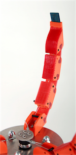
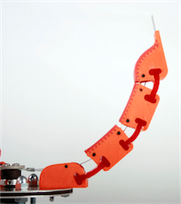
The final finger design is made using fused deposition modeling and is the culmination of two previous iterations. While the second version had three fingers and a thumb, the final version was simplified to contain only three fingers. They consist of four “U” shaped segments, all connected via a flexible polymer. The lowest segment is not actuated, but used only to attach the finger to the palm with two 6-32 machine screws. One of the screws acts as a pivot point around which the finger can be rotated and reoriented. The second screw secures the finger in the desired position.
The other three finger segments have soft Vytafex pads on the inside surface to help the hand to grip objects. At the end of each finger, there is a slot in the plastic that allows a spring steel “fingernail” to be inserted and removed as necessary. The fingernail has two sides, a pointed and a flat side, each of which are useful for specific objects. Inside the fingers, there are steel dowel pins that confine the cables which actuate the hand. The cables are connected at one end to the fingertip and at the other end to the winch that attaches to the shaft of the motor.
Transmission
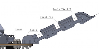
Power is transmitted throughout the hand via steel cables. The cable runs straight from a spool on the motor to the base of the fingers, and is routed in as straight a manner as possible (so as to reduce internal resistance). The cable runs over dowel pins through the finger sections and terminates at the final finger section, where it is attached to the finger.
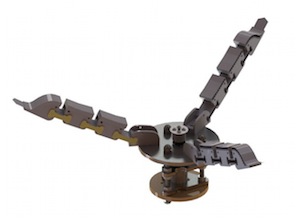
Our design has changed significantly over three iterations: our original design included a number of pulleys which routed the cables in a circuitous path. This was intended to produce torques inside the finger which would rotate the fingers about pin joints.
With our second iteration, we decided to use polymer joints instead of fixed rotating joints, which necessitated a redesign. We repositioned pulleys to accommodate the polymer and still provide torque to the finger sections. However, we found that the pulleys produced a great deal of friction, preventing the motor from driving the fingers.
In our final iteration, we decided to eliminate pulleys entirely and simply pull the fingers using the cable, rather than produce internal torques. This resulted in a dramatic decrease in friction, and allowed the hand to actuate as intended. While the cable routing within the fingers allows for easy transmission of motion, the geometry of the fingers limits their mobility. Much of the effort from the motor is wasted bending the fingers to the proper closed position before a proper grip can be established, which hampers grabbing small objects or handles. This would be one of the main issues to improve in future iterations.
Overall, the transmission in our final prototype works well, and provides a very smooth actuation.
Power
Power is provided by a Vigor Precision DC motor, model number BP6-N12R280-2685D. The motor supplies a maximum of 5.5 kgf*cm (4.77 lbf*in) at 21.0 rpm, so it is not very powerful. The output shaft is directly connected to the winch, which pulls on the the drive cable. More information on finger actuation is provided in the “Transmission” section. The motor is connected to a motor controller, which is in turn wired to a wireless receiver, which talks to a standard hobby RC transmitter. This allows remote control of hand actuation.
Fabrication
Fabrication of the hand consisted of 3D printed thermoplastic for the fingers, poured polymer for the grips and joints, waterjet-cut sheet metal, and laser-cut medium density fiberboard (MDF) for the structure.
None of the sheet metal needed to be bent, therefore the parts were ready to assemble after they were deburred. Holes on the sheet metal and MDF were loose fitting to allow bolts to make assembly and adjustments easier; however, some holes were deformed from waterjet cutting which was easily fixed by filing them to a larger size. The MDF pieces were sandwiched between identical sheet metal pieces to provide more structural integrity.
The rapid prototyped fingers had the longest fabrication time. After being printed, the polymer matrix composite (PMC) was poured into the joint molds and Vytaflex-10 was poured into the grip molds and had to set for at least 24 hours. There was a problem with the filler material in a mold on one of the fingers not dissolving completely in the lye bath. Placing the finger in another lye bath fixed the problem but resulted in increased fabrication time and ceased parts of the assembly process.
Future Improvements
Through multiple iterations, we found that friction and internal resistance are huge concerns with cable-driven systems such as this. Resistance to motion dramatically increases as cables are forced to bend and contort, diverting limited force from a motor to fighting internal resistances rather than doing useful work. Limiting cable bends is one of the most important concerns in this sort of design.
As mentioned in Transmission, the finger geometry is not optimized for grasping small objects or handles - a simple introduction of curvature in the unbent finger state would help alleviate this issue.