Introduction
In this project, we were tasked with creating a mechanical hand to compete with against our classmates to pick up a variety of objects to test different aspects of the hand’s capabilities. The hand would be judged in four different categories:
- Mass held by the hand
- Range of grip radius
- Aesthetics
- Dexterity
To test dexterity, several objects ranging in size and weight from a coin to a hand drill were available, including a pencil, a piece of paper, soap, and an ice cube. All attempts at lifting objects had to be made in 15 minutes or fewer.
We had to make four prototypes of our hand. The first was a model made of foam, the second a working prototype made of 1/8 inch plywood, 0.05" 5052 aluminum, and 1/8 inch or 1/4 inch plastic (Delrin). The third had to be made completely of less than 200 grams of 3D-printed plastic (PLA) and polyurethane rubber. The final prototype, which was used in the competition, had to be made with a combination of these. Teams were allowed 100 grams of PLA, and a total top-view surface area of 18" by 18" of combined plywood, aluminum, and delrin. There was a $25 budget to purchase materials from McMaster.
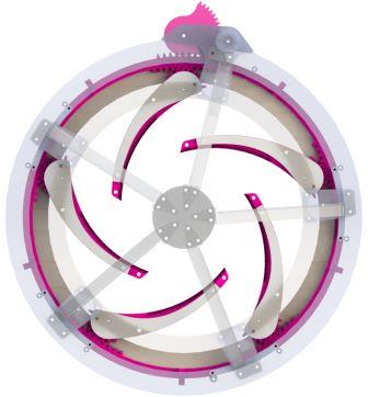
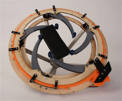
To these ends, we chose to proceed with an iris design with 5 fingers. This would allow for easy gripping of both large and small objects, with the only size constraint being the inner diameter of the iris. It would also allow for lifting non-uniform objects by facilitating at least three points of contact between the objects and the fingers.
Design Overview
We considered a broad spectrum of ideas for our hand’s design. There was an initial assumption in our group and the class at large that a “mechanical hand” must emulate a human hand. However, in considering the weaknesses of a claw, especially with regards to lifting cylinders and small objects, we decided to interpret the “hand” more broadly as a grasping mechanism. We concluded that an iris mechanism would possess the versatility to handle most of the proposed objects with relative ease.
We predicted that an iris mechanism would have the following advantages over a claw design:
- An iris’ “fingers” come together to a point in the center and can theoretically grasp small objects with no lower limit on the size of those objects.
- An iris can support an arbitrary number of fingers, allowing us to use a five-fingered grasp. This five fingered grasp has the ramification that even if an item is grasped off center, or has an odd geometry, it can be grasped between 2, 3, or 4 fingers.
- An iris can be dropped down to flush with the surface supporting the object to be grasped and then closed comparatively “blindly”- that is - without great precision or fine height maneuvering to grasp small objects.
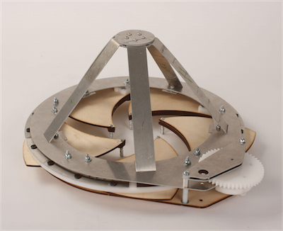
As was required, after the foam sketch model, we had three working iterations. The first was made completely of wood, Delrin, and sheet metal. We made our gears out of Delrin, our cage and top support plate of aluminium sheet metal, and our bottom support plate and fingers from wood. We designed a “cage” on top of the hand to allow us to grasp objects as large as a basketball. This design was heavy, but otherwise operated quite well overall. We did have difficulty in fabricating gears out of the laser cut Delrin. The fingers operated well in terms of rigidity, but did not have a compliant surface for grasping hard or low friction objects.
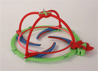
The second iteration was entirely 3D printed. We experimented with different infills and thicknesses for the 3D printed cage, and we did not use a support ring, instead opting to use guide poles on the outside and inside of the ring gears to constrain its motion. This iteration operated comparatively poorly. There was a lot of slop because the cage would flex under pressure, putting our fingers and ring gear off-center. However, this iteration was a fantastic guide for decisions made in the final iteration. We also learned from this iteration that 3D printed gears operated well and were easy to work with. We added a compliant rubber surface to the face of the 3D printed fingers, and integrated the finger gearing into the finger itself. These fingers proved to be highly effective, strong (though flexible), and lightweight.
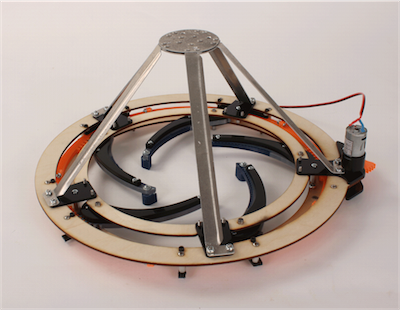
From what we learned in the first two iterations, we decided that we wanted to have support plates to constrain motion, and stabilize the fingers. We chose to make our fingers thinner in than we had in the first iteration, but we added rigid Delrin supports to prevent them from flexing as they had in the second iteration. Additionally, we used a layer of molded rubber on the inside edge of our fingers, like in our second iteration, to increase friction. Our cage mimicked the first iteration, but with a bent strut to prevent bowing. We 3D printed all of our gears. We also tweaked some small variables from previous iterations: we changed the pitch of our gearing for decreased play between mechanisms, added slippery Teflon tape and washers to bearing surfaces, and used greased dowel pins and bushings as axes for the fingers.
Overall, our design was extremely effective. Before the competition started, the class as a whole assigned point values to the different tasks the hands would be undertaking. Overall, our hand won 103 points. For comparison, the lowest team's score was around 25 points, and all other teams scored in the mid-70s.
Structure
Iris Structure
Our hand's primary mechanism, an iris, provided a unique set of structural considerations. First, providing a rigid, planar bearing surface for the fingers and the syncronizing planetary gear. Second, designing structures that could accomodate our necessary inner diameter while not exceeding the dimensional constraints of our materials budget.
Our team tailored the geometry of our iris structure by the material constraints of the first two prototypes, and designed the third prototype's structure based on what we had learned. In our first prototype, our material constraints allowed us to use only thin (1/8") plywood, delrin (a rigid plastic), and aluminum sheet metal, with each available in limited quantity. The delrin was quickly allocated for fabricating gearing because delrin has good material properties for that application. That left the wood and aluminum for the construction of a ring structure to support the fingers and planetary gear. We did not have enough material to construct both the top and bottom plates out of the same material, so we fabricated the top plate from aluminum and the bottom plate from wood, and spaced them with stand-offs. In testing, this approach functioned, but we realized that one error in our design was that the planetary gear had no vertical constraints and could freely move up or down on the outside of the finger gearing. Despite this design issue, the overal structure was fairly rigid and we did not encounter any serious issues of note.
In our second iteration, we were limited to using a 200 grams of 3D printed plastic (PLA). Because large planar parts would be too materially expensive for our budget of PLA, we redesigned our iris structure to be virually nonexistant: rather than a large ring such as in the first prototype, we suspended the fingers off of the ribs, and connected the ribs together with very thin support struts. The thinness of these support struts, coupled with the comparatively low rigidity of PLA caused this iteration to have significant bowing issues. As the fingers came together on an object, the normal force resulting from grasping the object would cause the ribs to deform into a less-than-ideal configuration for grasping.
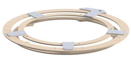
Taking a lesson from the second prototype, our team moved back to using a ring structure for the third and final prototype. Material constraints for this prototype were determined such that we had one budget for all planar parts (anything wood, delrin, or aluminium). Wood has a higher rigidity than aluminum, so we opted to use that in our final iteration. Due to size constraints in our material budget, we designed the rings for this iteration to nest together when cut. We added teflon tape and washers to minimize friction between bearing all bearing surfaces and moving parts. Additionally, we added delrin blocks to vertically constrain the planetary gear. With these improvements, the structure of our final iteration worked extraordinarily well without being prone to any of the issues of either the first or second prototypes.
Finger Design
A critical part of making our hand work was guaranteeing that the fingers would not break when lifting heavy objects. Our first working prototype had very wide fingers made of plywood with thin wooden supports. The second working prototype had 3D printed fingers. Though the wood was less compliant than the 3D printed PLA, we used the 3D printed fingers in our final prototype so that we could have molded rubber grips on the inside edge of the fingers. In order to prevent the fingers from bending, we experimented with increasing the infill of the fingers, the thickness of the fingers, and the width of the fingers. However, for the extra PLA used, we found the increased strength insufficient. For our final prototype, we decided to add a Delrin support to the top of each finger. 0.25" Delrin bends much less than PLA, so we were able to get the strength we wanted without using extra PLA.
This was a successful tactic, as we were able to lift 12 pounds, the maximum weight available to us, and our hand was one of only two that did this successfully.
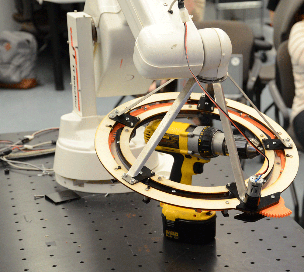
Mounting
We percieved two major design options for mounting the hand: Mounting the wrist to the side of the hand and building a "cage" structure up from the top of the hand to mount to the wrist.
A side mount for the wrist would be simpler in design and manufacture than designing and fabricating a cage structure. This approach would take less labor and material. However, this configuration has two distinct disadvantages. First, the wrist would only support the load from one side. This would mean that, when initially grasping and lifting a load, the force of the weight of the load would exert maximum torque on the wrist because the direction of the force would be approximately tangent to the axis of rotation. Second, the distance from the load to the wrist (~ 7.5" radius) would be greater than building up a cage that allowed just enough space for our largest anticipated object (~ 5" radius). This in turn would lengthen the lever arm of the load and increase the torque on the wrist.
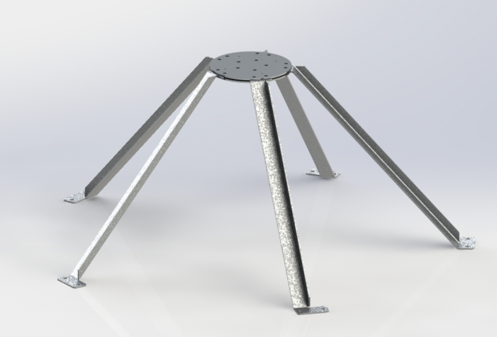
By comparison, a top mounted cage structure would put the wrist directly over the load. This approach would require additional labor and material, but had two advantages. First, the load would be balanced: the wrist would be located directly over the load, so there would be no significant torque on the wrist when initially lifting a load. Second, because we could design a cage structure just large enough to accomodate our largest sized object, we could decrease the distance between the wrist and the load. This minimizes the magnitude of the torque that could be exerted about the wrist. These two advantages meant that a top mounted design would confer an advantage in lifting heavier loads than a side mounted design would.
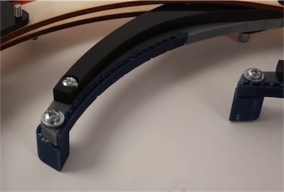
After consideration of the above two options, we elected to mount our hand from the top with a cage structure that sits on top of the iris mechanism. In our first iteration prototype, the cage structure consisted of flat strips of aluminium ("ribs") extending from the surface to a central hub. We had no major issues with these ribs, but were slightly concerned about the the potential of the ribs bowing when under compression. In our second iteration, we were required to fabricate everything with only a small budget of 3D print plastics (PLA) and no other materials. To meet this challenge, we made the rib structure as thin as possible, but experienced issues with bowing due to both the thinness of the ribs and the low rigidity of the PLA. For our final iteration, we opted to return to using the aluminum ribs from our original design with two modifications. First, we made the ribs thinner in order to use less material; second, we added a slight bend into the ribs so that they had some resistance to bowing. This design performed with no issues in our final prototype.
Transmission
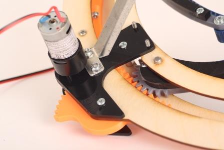
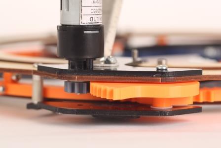
The transmission of our hand consists of planar spur gears. This method was initially chosen because of both the circular symmetry of our hand the and the ease of creating flat structures with the laser cutter and the waterjet cutter, specifically for the first iteration. For the second and final iterations, the fingers were 3D printed with gear teeth built in to solidify the power transfer to the fingers. The large ring gear was chosen to be 3D printed as well, to prevent the difficulties with removing incompletely laser cut gears. It carries power to each of the five fingers from the power system. This connection is a series of gears between the outside of the ring gear, and the motor.
Power transmission and ratios are as follows:
- Small Motor Gear to Large Motor Gear
- 10 teeth to 50 teeth = 5:1 gear ratio
- Large Motor Gear to Pinion
- Same physical part = 1:1 “gear ratio”
- Pinion to Rack
- 18 teeth to 165 teeth = 165/18 ≈ 9.2
- Rack to Large Ring Gear
- Same physical part = 1:1 “gear ratio”
- Large Ring Gear to Fingers
- 150 teeth to 21 teeth = 21/150 = 0.14 gear ratio
The total gear ratio is therefore 5 * 1:1 * 165:18 * 1:1 * 21:150 ≈ 6.4:1. This transmission reduced the closing time of the hand to 1 second and gave us 10in-lb of torque to all the fingers. Speeds in this range are ideal for grasping, as it is fast enough to close nearly instantly, but also slow enough to allow precise control on slow motor speeds. Clamping force for our hand was much lower than the structure was capable of supporting, but we found the trade-off of force for speed to be acceptable. Given a chance to redesign the transmission, we would have reduced the gear ratio further (by a factor of three) by means of a worm gear to provide steadier (although slower) control of the fingers, less back force, and higher clamping force.
To reduce deflection of the structure while clamping, the pressure angle of the teeth was reduced from 20° in our two prototypes to 14.5° in our final hand. The transverse force on the gears in the final version is 70% of the same force for the same driving force in our two prototypes.
Power
Power to our hand is provided by the motor, which we were given at the beginning of the course. The motor is a Vigor Precision BP5-N40R280-2685D and can provide up to 1.6in-lb of torque, and has a free speed of 65rpm. It is connected to the robotic arm which the hand mounts to at the test station. Our team sets the motor speed with a remote controller. A 3D-printed spur gear is press fit onto the motor’s D-shaft to transfer torque to the transmission system.
Fabrication
For each prototype, we were given a different set of material and fabrication constraints. For the first prototype, we were limited to a specified quantity of plywood, delrin sheet, and aluminum sheet stock. All fabrication techniques were subsequently planar; laser and water-jet cutting, and fasteners were limited to standard. With the second prototype, we could only use 3D printed parts with a limited weight of PLA plastic, two part composite material, and standard fasteners. The final prototype allowed the use of all previous materials and techniques in smaller quantities and a budget to buy specialty hardware.
We chose to create the outer rings of our hand out of plywood because of its rigidity; any flex in that area contributed to slop in the finger-closing mechanism. The mounting cage was created from waterjet cut aluminum for its strength, flexibility, and small thickness. It was challenge to bend the metal to the exact angles we designed for, yet the ability to improve it incrementally was helpful for this. All geared parts were 3D printed due to the precision offered by that fabrication method over all others available. The ability to create molds for composite material on the fingers to aid in gripping objects with a 3D printed part was another driving factor for printing the fingers. The fingertips were created using a 3D printed skeleton and composite body. The compliance of the composite allows the material to conform to small or irregularly shaped objects.
Future Improvements
The greatest challenge we faced in our design was creating the optimal geometry for our iris mechanism. Ensuring a flat and rigid enclosure for the gears to eliminate slop takes either a significant amount of material or a clever design. The greatest solution we found were large, one-piece rings to guarantee concentricity and aid rigidity. The 3D printing constraints on our second prototype did not allow for such pieces so, while the hand did work, there was significant slop and lag between the fingers due to the entire design being composed of smaller, thinner, much more flexible parts.
Our design itself has a fixed size limitation; it cannot lift anything that it cannot get its fixed diameter outer gear around. This means its size is dictated by the largest thing it is expected to grip.