Introduction
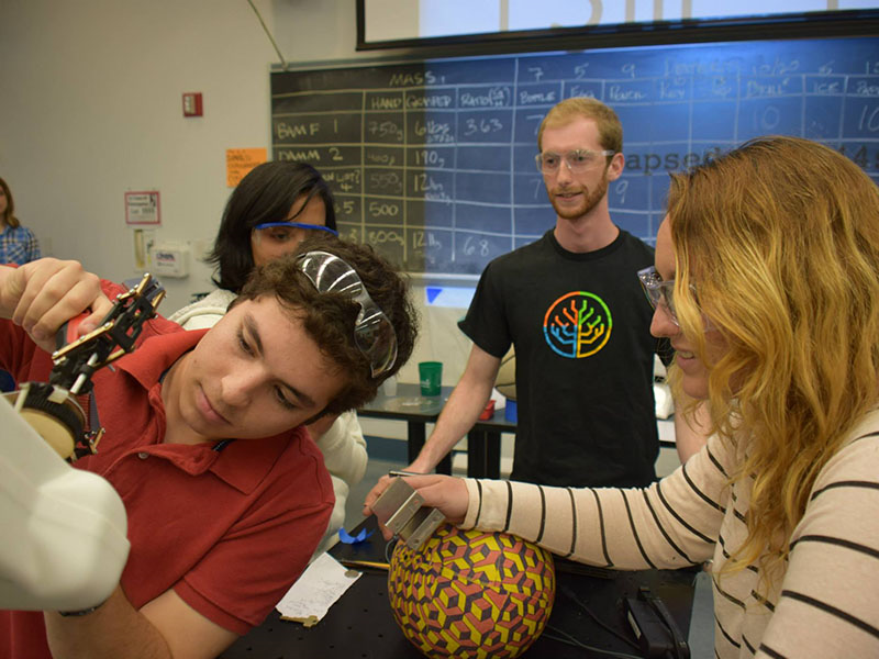
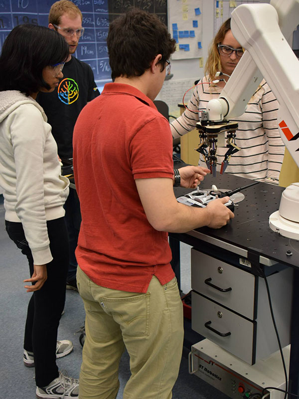
 Our Mechanical Prototyping class has spent the past month and a half creating robotic hands to compete in a final challenge to see which hand is most versatile. While the task at hand (pun intended) may not seem to be the most exciting, it allowed for a large diversity of potential designs and encouraged students to explore the process of defining their own constraints and solutions.
Our team’s main goal for this project was to create a hand which could pick up a wide variety of differently shaped objects. We accomplished this through three iterations using a unique compliant mechanical linkage for fingers which could adapt to irregular forms while still providing a strong grasping force.
We had different material constraints for each iteration of the hand. For the first, we had one 15in x 20in sheet of 1/8in thick Baltic birch plywood, one 16in x 16in sheet of 0.050in thick 5052 Aluminum stock, and one sheet of 8in x 12in 1/4in thick Delrin. For the second iteration we were limited to 200g of 3D printed plastic. For the final iteration we were allowed 324 square inches of planar material (Delrin, aluminum, and plywood) and 100g of 3D printed plastic. We also had $25 to buy anything from McMaster-Carr, which we used to purchase E-rings and other hardware.
Design Overview
In our first prototype, we focused mainly on power transmission. Because of the limitations of our material constraints and their associated manufacturing methods, we knew we would be unable to build fingers as complex as we wanted. Thus, we decided to postpone that design decision. The main idea behind our transmission system was to turn the rotational motion of the motor into linear motion in order to close the fingers, which we accomplished with a threaded rod. We were happy with the fast but controllable closing speed, high grasping force, and durability that this system gave us. We decided to carry it forward into the next prototype. However, the idea of a sliding “thrust plate” which actuated all three fingers at once created a hand that was overly large and unwieldy, and caused too much binding friction. While we had incorporated into our design the ability to rotate fingers to grasp different types of objects (spherical, cylindrical, or planar), we decided that this would be unnecessary with the more dextrous fingers we hoped to make.
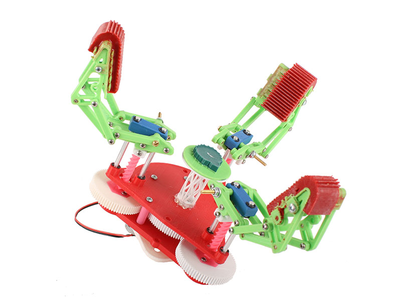
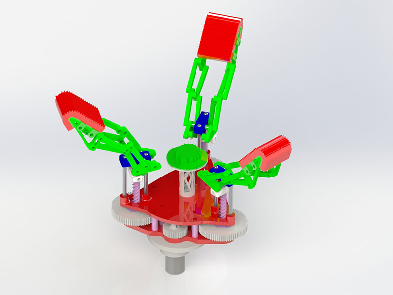
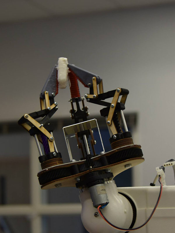
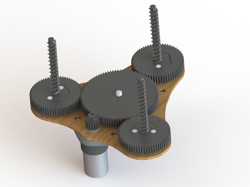
Our second prototype was devoted largely to designing our fingers. We were inspired by a Japanese food-handling robot called the D-hand (which can be seen here) to create an underactuated (meaning more directions of motion than actuators) linkage system. By varying the amount of friction in various joints we were able to make the finger close from the bottom up, bending at a joint each time a lower link encountered resistance, allowing it to encircle an object. This design was very appealing, as it allowed us to pick up a variety of shapes, but each finger was very wide and not as rigid as we wanted. For this prototype we also changed our transmission to a planetary gear system. Each of three outer gears had a threaded rod attached which actuated a finger. This allowed us to actuate all three fingers at once as in our first prototype, but allowed for a much smaller and more elegant design.
Our final iteration is very similar to our second, but includes a series of changes to improve grasping ability and to comply with material constraints imposed by our professor.
Structure
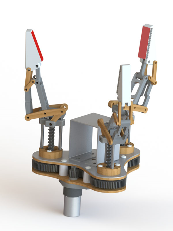
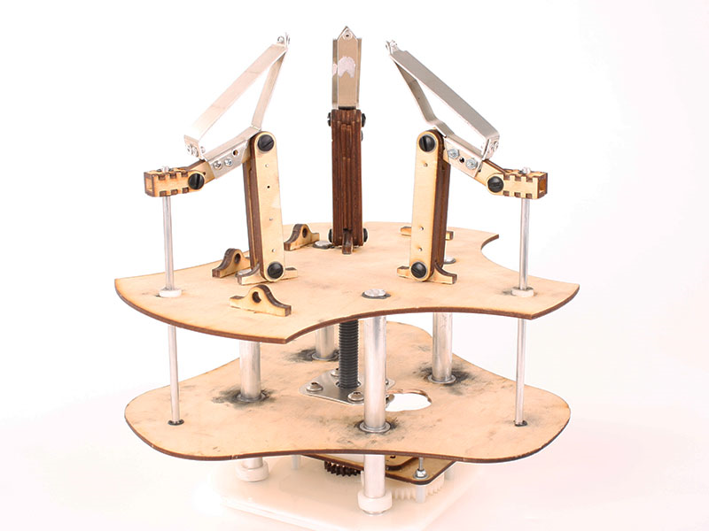
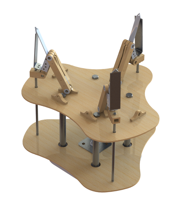
The structure of our hand is composed of 4 parts: the transmission box, attachment plate, fingers, and palm plate.
 The transmission box consists of two parallel plates. They sandwich together the gears and provide a mounting place for the fingers and palm plate. The top (closer to the fingers) plate is composed of sheet metal and wood epoxied together to provide strength, as that is where the upward forces of the fingers will be applied. We attached it with the aluminum side up, as the metal is provides resistance against the compression that would occur due to the finger forces bending the plate. This plate was then bolted to the bottom (wooden) plate with spacers in between to keep them from pressing on the gears, and held in place with lock nuts.
The attachment plate, made of Delrin plastic, allows us to more easily connect our hand to the robotic arm we use to manipulate objects and serves as a support to ensure that the motor (mounted to holes in the bottom wood plate) remains rigid while powered. It connects to the transmission box via the bolts that keep the box together, limiting the amount of hardware we need to use.
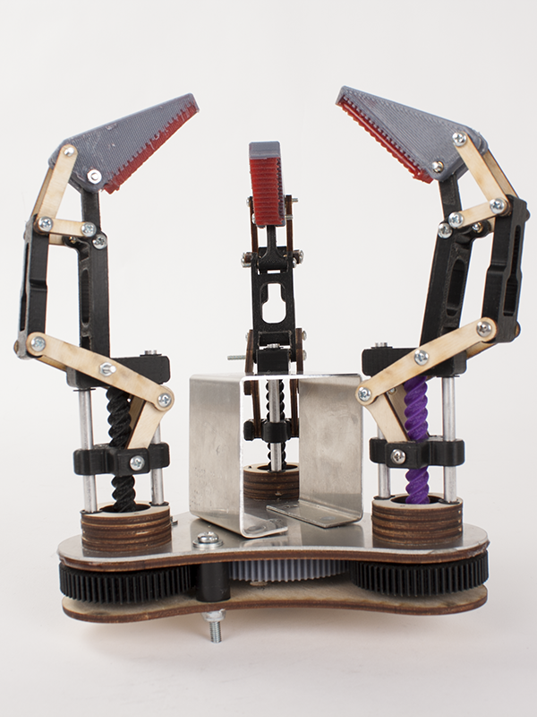
The fingers consist of a group of 16 parts linked together. The pieces are made of either birch or PLA depending on their function, and are held together by a series of bolt pin joints so that they can rotate freely with respect to each other. They were designed to fit together so that each finger is as narrow and sturdy as possible. The tip of the finger includes a compressible polyurethane pad that can deform around an object being grasped, increasing the hand’s grip. Each finger mounts to a plastic block which is constrained to the top of the transmission box by two aluminum rods. These rods are held to the block and plate by E-rings snapped into grooves in the rods. They are supported by rings of wood stacked on the top of the transmission box, creating a strong and rigid structure.
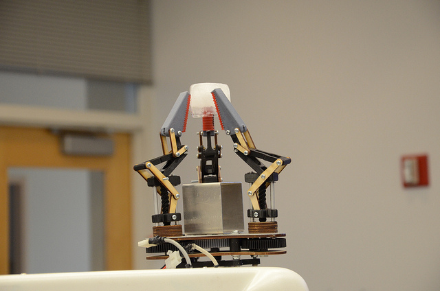
The palm plate is a simple sheet metal shape that gives the fingers a flat surface on which to grasp objects. It is attached to the top of the transmission box by a peg and hole joint, where short hollow plastic tubes are pressed into holes in both the palm plate and transmission box. Because any grasping force acting on the palm plate would be pushing it onto the transmission box, this attachment serves only to locate the two with respect to each other and to keep the palm plate on the hand while it is upside down.
Transmission
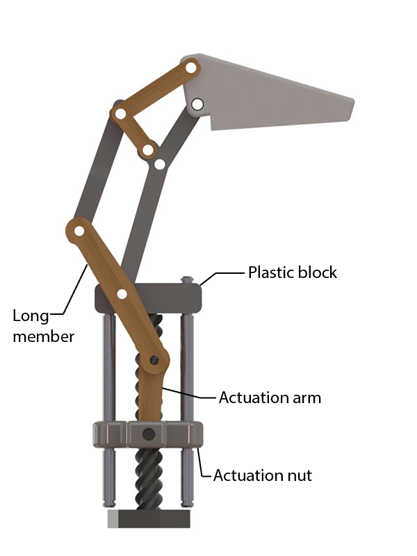
Our final prototype has the same transmission system as our second, with the torque of the motor transferred to the threaded rods via the gearbox, geared down with a ratio of 1:4. An actuation nut riding on each threaded rod rises up and down linearly, serving as the first locus (point) in the mechanical linkage system of the finger and pushing the actuation arm up and down. The actuation arm then acts upon the long member of the finger linkage, essentially rotating the entire finger about its attachment point on the plastic block.
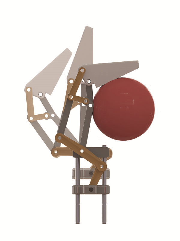
From there, the finger closes around an object just as our second prototype did. We tweaked the design to minimize the number of parts necessary and make the entire assembly more compact and strong. This largely eliminates the wobble we saw in our second iteration, allowing us to grasp objects more strongly without fear of the fingers deflecting or breaking. Making the fingers narrower allows them to come together at a sharper point when closed, meaning we can pick up smaller objects.
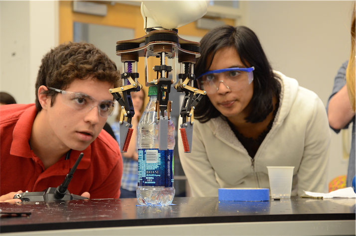
One of the unique aspects of our fingers is the ability to perform two types of grasp: precision and power. In power grasp, the fingers close around an object, gripping it into the palm plate. This is useful for items which are very large or heavy. In precision grasp, an object is held between the fingers and is not brought in towards the palm. This helps us pick up small or flat items. We are able to switch between these grasp types easily by adjusting the position of one joint of our fingers. While precision grasp is achieved by essentially locking one of the members in the finger linkage, the assembly still retains enough underactuation to adjust to the shape of an object.
Power
To power all three iterations, we used a Vigor Precision LTD BO-P5 motor with a built in planetary gearbox. With a maximum speed of 131 rpm and maximum torque of 1.8 kgf.cm, this motor was small but powerful enough to provide our hand with reasonable grasping force. It was fast enough to close the hand quickly while still being controllable. The motor interfaced with the rest of our transmission system via a 3D printed PLA gear press fit onto the motor’s D-shaft.
Fabrication
Because our hand was composed of a variety of materials, we employed several manufacturing methods in its construction. All wood and Delrin parts were laser-cut. While we originally had difficulty with undersized or oversized pieces, once we had tested and fully understood the tolerances and precision of the laser cutting machine we were able to easily and quickly create parts with complex shapes.
PLA parts were 3D printed with a Makerbot. Again, we tested the printer until we knew its abilities and limitations, and were able to create pieces that fit into our assembly with minimal post-processing.
Our aluminum parts were either cut with a water jet cutter (the top plate of the transmission box) or cut and bent with sheet metal tools (the palm plate), depending on their complexity. The polyurethane finger pads were made by filling a 3D printed mold with liquid polyurethane, allowing it to cure and become solid, and then removing the part of the mold that covered the pads. We initially encountered problems with the 3D printed molds leaking, but redesigned them to be able to hold liquid.
Overall our parts were well designed for manufacturing as they were mostly machine-created (printed or cut). However, we found that our palm plate was not conducive to fabrication as it incorporated a bend impossible to achieve with the sheet metal tools at our disposal. We completed the bend with hand tools which, while functional, was not ideal.
The phase of fabrication in which we spent the most time was assembly. We press-fit threaded inserts into any wood or PLA part that had to interface with a bolt, which took careful planning and a significant amount of time.
One design factor that we took into consideration in our second and final prototypes was modularity. Each finger could be fully assembled by itself, as could the gearbox. Then, the pieces could be easily bolted together (with an unfortunately large number of bolts). This afforded us two large benefits: speed of fabrication (as all subsystems could be worked on in parallel), and easy disassembly and reassembly in the event of a part failing.
Future Improvements
While we are very happy with the performance of our final iteration, we have identified a few ways in which we could improve it if given more time.
First, we would like to add sharp fingertips to our fingers so that they could grasp planar objects lying flat on a planar surface. Our hand is optimized to pick up irregular, quasi-spheroidal shapes of medium size, and adding these tips could greatly increase the range of situations in which our hand would be useful.
Next, we would like to include the ability to change the angular orientation of fingers on our hand (as was possible in our first prototype). This would allow us to tailor our hand better to each object we want to pick up, rather than relying only on the underactuation of our fingers.
Then, we would like to redesign our palm plate so it would be easier to manufacture and held on more sturdily.
Finally, we would like to improve the use of hardware in our design. Because of the many pin joints in our fingers, we needed a large number of threaded inserts, bolts, and nuts. Redesigning our actuation ordering method (perhaps switching from friction to springs) would allow us to replace this hardware with something much simpler, like dowel pins.
If we were to give advice to future designers of these hands, we would advise them to consider the size and shape of objects they are designing the hand for. We would recommend that they carefully plan out hardware to eliminate interference. Lastly, we would warn them to keep their design simple for ease of assembly.
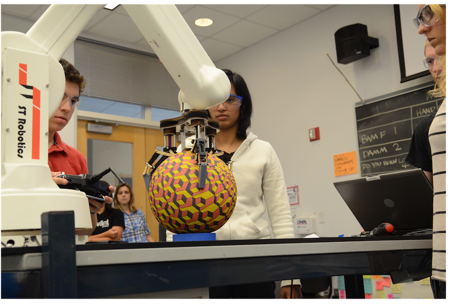
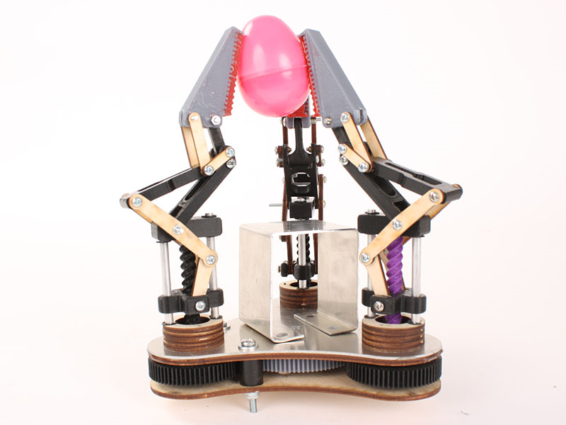
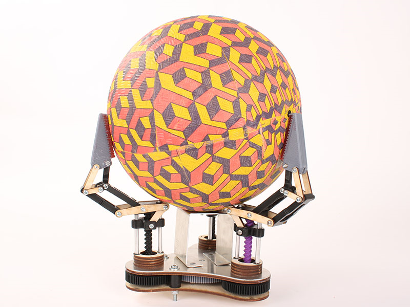
The Hand in Action