Introduction
For the final project in Mechanical Prototyping, a course at Franklin W. Olin College of Engineering, our task was to design and fabricate an underactuated hand using various materials, with a focus on iteration and becoming comfortable working in each medium available to us. This hand must demonstrate the ability to lift an array of objects, varying in size, shape, and weight. We brought this project through three major iterations, with different material limitations for each. For the first iteration, we were tasked with using solely delrin, wood, and sheet metal. This challenged us to explore the planar material space, while also getting us comfortable with working with the various sheet metals tools in the shop. For our second iteration, we were limited to 200 grams of PLA. We were forced to think creatively about how we could take our first iteration and find creative solutions to utilize the 3D printer to the best of its ability.
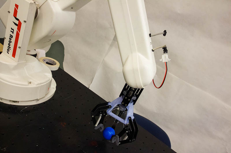
For our final iteration, we were only given 18’’x18’’ of planar material (1/4’’ delrin, 1/8’’ delrin, 1/8’’ plywood) and 100 grams of PLA, used for the Makerbots made available to us. We were excited to make the most of being able to use all previous materials, and really enjoyed refining features from our old prototypes while developing completely new ones to create our final product. For the final competition, our hand performed well, getting 1st in Aesthetics, 1st in Heavy Lifting, and 2nd in Dexterity.
Design Overview
 When first sitting down to try to design a hand from scratch, we pulled inspiration from a gear puller. We modeled our first iteration after a gear puller made availabe to us, making slight adjustments to add in places for underaction. We really wanted the underactuation to be present in our final design, as it disappeared in the middle iterations. In addition, one member wanted to experiment with herringbone gears in the transmission system for our final iteration, so we attempted to utilize herringbone gears and their inherent special features for our hand.
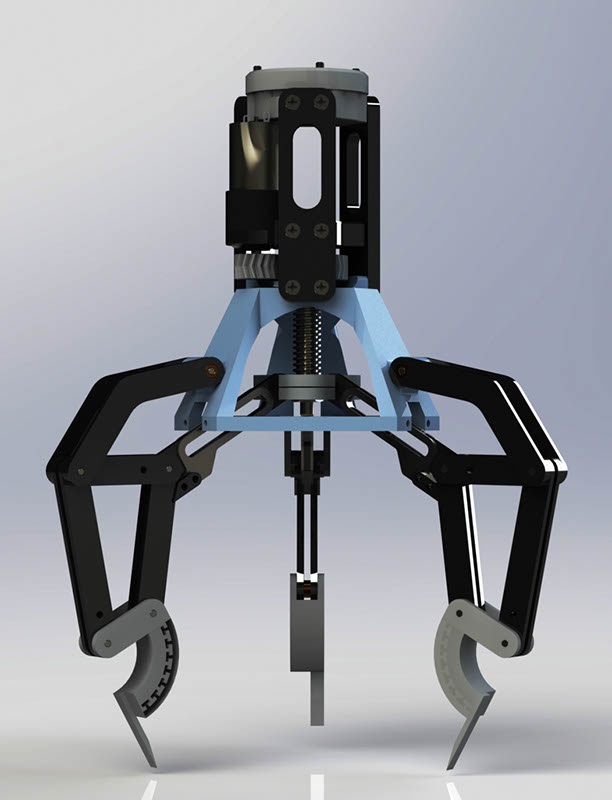
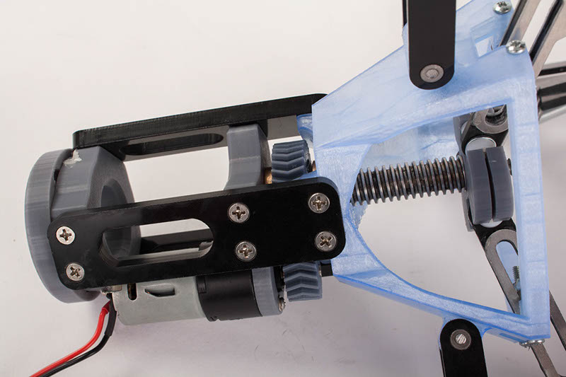
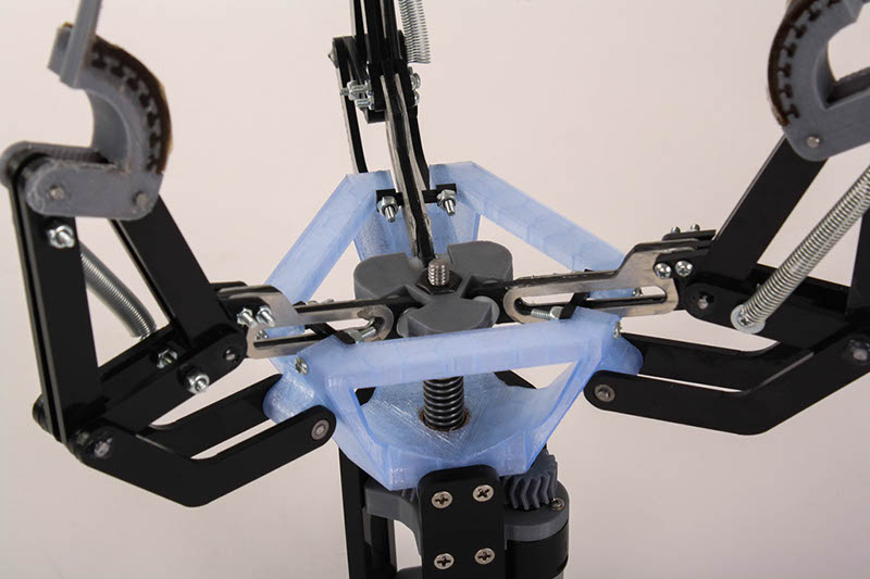
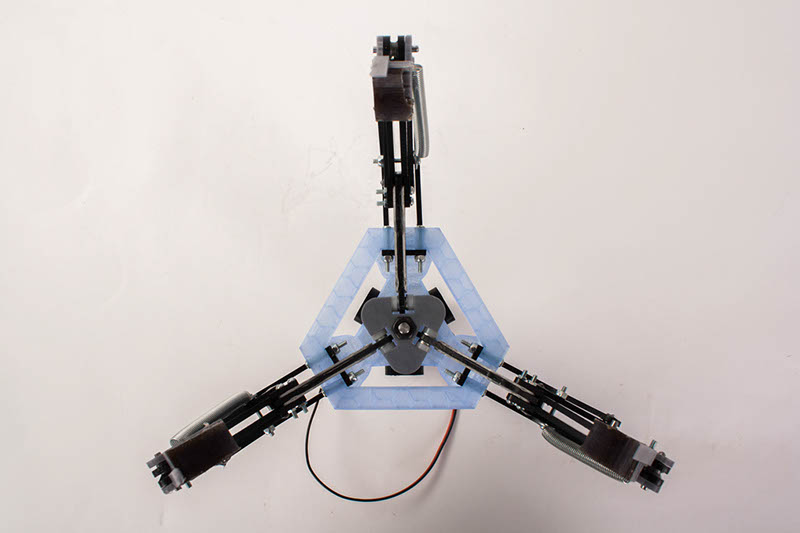
The overall structure of our hand is a simple three finger design where rounded tips come to a point. There are “fingernails” on the tips to scoop up tiny objects, and the tips themselves are coated in VytaFlex (Shore 20) to increase grasping ability. The fingers themselves are an under actuation system coupled with a mechanical stop and a spring, which resists closing the hand. This underactuation utilizes a four-bar linkage with the outer bar being fixed to the frame of the hand. The inner bar is vertically moved by a threaded rod, which was constrained by two nuts in the frame. A herringbone gear on the threaded rod was turned by a herringbone gear from the motor with a 1:2 gear ratio, constraining the threaded rod to vertical and non-torsional movement.
 While our design is fairly simple, the unique features we have are the “fingernails” and the transmission system consisting of herringbone gears. Herringbone gears are used rather than spur gears because they constrain vertical movement, so we could eliminate extra material. The mounting system was very quick. We would screw in a circular piece with four curved-rectangle holes. Our hand, with four hooks on top, would easily fit into these four holes. One quick turn locked in our hand all in a time under thirty seconds. Our design was somewhat conventional, but we were able to optimize it to perform well for the challenged we faced. We believe we were successful in this attempt due to our results in competition: we came first in heaviest object held to mass ratio, first in aesthetics, second in dexterity, and third in largest grasp to smallest grasp ratio.
Structure
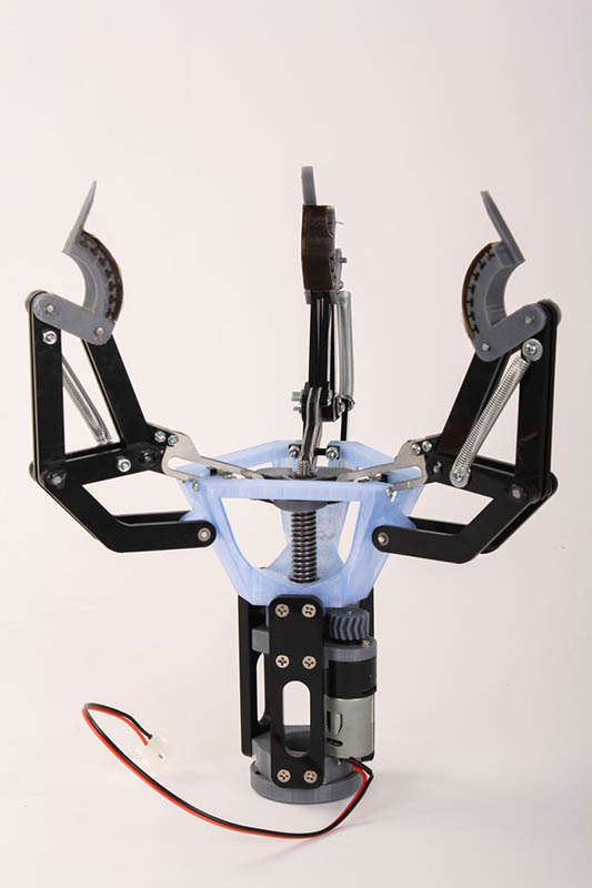
During our first and second iterations, our hand consisted of a frame, gearbox, and finger assembly. This led to some odd looking hands, mostly due to the fact that how the gearbox and frame fit together were afterthoughts of our design. We devised ways to fit a rectangular gearbox within a triangular frame, and although the results were functional, they were poorly designed.. For our final iteration, we decided to integrate our gearbox and frame, 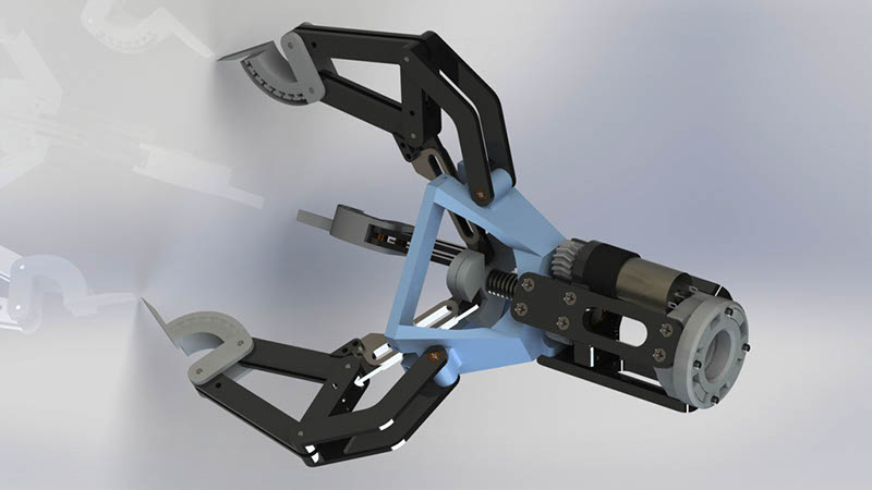 producing one complete structure that the finger assemblies would mount to. The results of this integration was a pseudo-triangular prism, consisting of 3D printed parts, with delrin beams holding the box together vertically. Although we were not able to adjust the structure of our design to allow for different finger configurations, we were able to provide a sturdy, aesthetically pleasing design that provided more than enough support while remaining within our tight material constraints.
Transmission
Our transmission consists of two herringbone gears, a powered 16 tooth gear going to a 32 tooth gear with a nut press fit into it. This provides a 1:2 gear ratio and because the gear is constrained by the bottom and top of the gearbox, the turning of 32 tooth gear caused the threaded rod attached to the nut to move up and down.
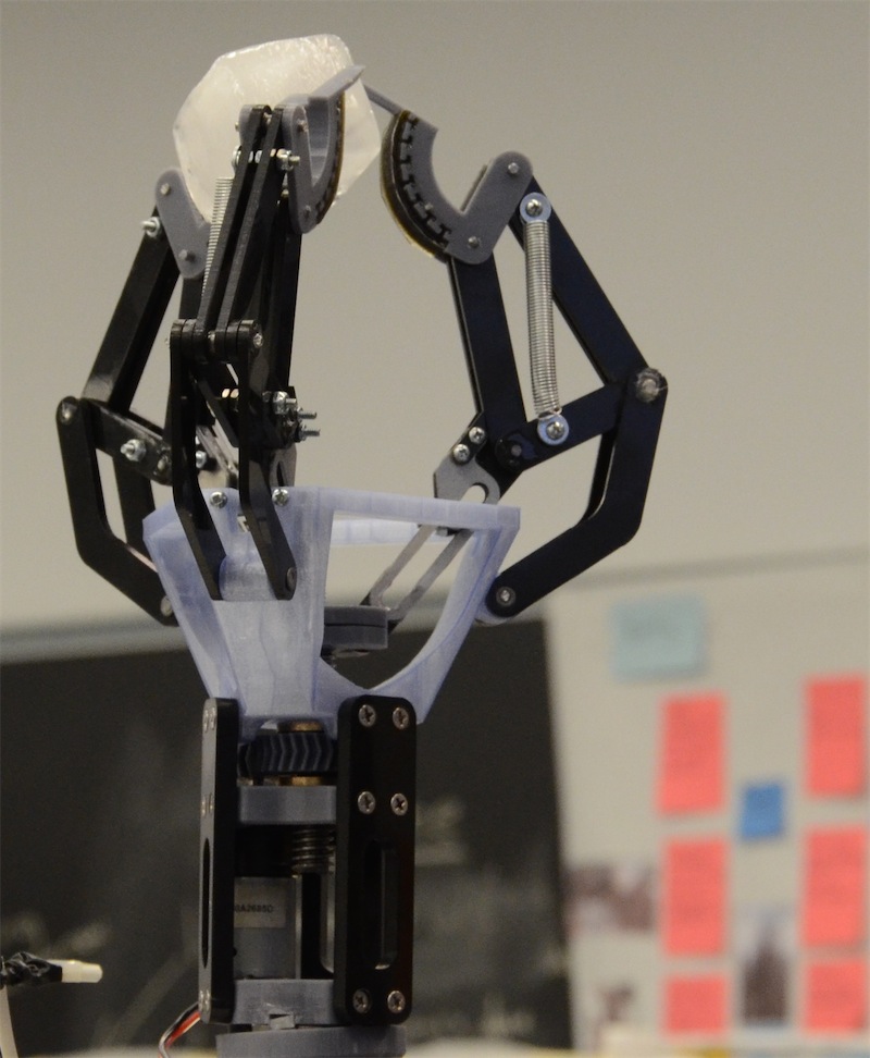
As the threaded rod moves up and down, it pulls a bar on the fingers with it. This bar pulls on the inner side of the finger shortening the length of the inner side from the bottom of the frame. The outer side stays the same length from the bottom of the frame, forcing the finger to curve inward toward the middle. The fingers are underactuated, and have springs and mechanical stops so that all parts of the finger are fully constrained. The springs result in an open-type failure so that the motor 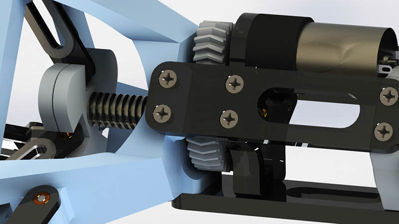 resists the springs as it pulls the fingers closed. The springs most affect the position of the finger tips when grasping an object. With this design, the finger tips stay angled open until the tip-circle diameter is about 3 inches. At this point, the mechanical stop activates forcing the tips to scoop up the tinier objects. Please see the videos tab to see these forces in action.
Power
Each team was issued a DC gearmotor and a standard Servo to power their hands. Our hand utilizes the DC motor, powered by the anderson connector near the end of the arm. The gearbox top consists of both holes for machine screws to mount the motor to the top, while also having a custom countersink to allow the motor to press fit into the lid itself. The combination of these two provides a very secure mount that allows us to be confident in mounting. The motor has a 16 tooth herringbone gear pressed onto its D shaft output, with help the herringbone’s centering force to keep the gear on the shaft.
Fabrication
We used waterjet cutting, laser cutting, and 3D printing for our hand. Because our fingers consisted of many simple bars, we simply laser cut delrin for essentially all the fingers. We used waterjet cutting just to sandwich several pieces of delrin for stability, but we did not use much sheet metal outside of that. These fabrication methods worked incredibly well for us because it was fast and the parts were all essentially exactly how we wanted them. The only problem that arose was that we did not plan accordingly for the kerf of the laser. Our holes were slightly too large so press fitting ⅛” steel shafts did not work well. Instead, we needed to epoxy the shaft to the sanded delrin holes. The same happened for the bronze bushings. We used 3D printing for the frame. Because the frame also consisted of the gearbox for the final iteration, it made more sense to 3D print the somewhat-oddly shaped frame. It made assembly much cleaner and simpler, and also allowed for a much lighter frame.
Future Improvements
Using VytaFlex is a very good idea. Designs should not be manufactured so that the points that grasp the object are hard and very constrained.. Everyone should acknowledge that the hand will not be perfectly manufactured in the end. Therefore, “manufacturing your hand on the premise that the points that grasp the object are exactly where the CAD shows” is very unreasonable. Future designers should design the tips of the fingers such that there is some form of leeway room to make up for random errors in manufacturing. Furthermore, having non-perfectly-constrained hands allowed for the ability to grasp some objects that we should not have been able to grasp. However, future designers should recognize that breaking your hand is very easy; we are one of few teams who did not break their hand in competition.
If we had the ability to design another iteration, I suppose we would initially optimize the finger tips. We did incredibly well in competition due to our tips, except for the largest ball to smallest ball ratio. Our design allowed us to grab under very flat objects, but the fingers were not designed to grasp incredibly small objects such as ball bearings. For that specific example, we would probably change the tip design such that when the fingers come to a point, two fingers have VytaFlex facing each other in a flat plane. For an object like a ball bearing, it could be sandwiched between these two VytaFlex planes and easily lifted. In addition, we would change the finger geometry so that it could lift larger objects. Due to the many bars involved in the finger, altering any length greatly altered the position of the fingers when fully actuated. Sadly, we did not think that we would need to lift a basketball for competition and did not design the fingers to do so. We actually were not worried about material constraints for the laser cut parts at all, so adjusting these lengths to fit a basketball would not be any trouble at all.