Introduction
Over the period of six weeks, students were challenged to prototype three iterations of a mechanical hand. Each iteration had specific material constraints and a single motor available. The final design would be judged for its own mass, size, dexterity, and visual appeal and compete in a class competition to test the capability of the hand to pick up items of various shapes, sizes, and weights within 15 minutes. Our goals were to have a three-finger design that had a transmission that operated simply and cleanly. Our extra goal, which was just for fun, was to have aesthetic themes for each iteration.
Design Overview
The materials we were allowed to use for the final model were the following: 100 grams of 3D-printed PLA, 18”x18” total surface area of planar material (⅛” plywood, ⅛” Delrin, 0.05” 5052 aluminum sheet metal), and $25 of parts from McMaster-Carr.
Taking these design objectives into account our team decided to utilize a cable driven design that would grasp by collapsing the fingers around the object. The hand would then release using a passive mechanism that would return the finger to its original orientation. We approached the first iteration with these objectives in mind and refined the following designs, adapting for issues that were not initially considered.
Operation of the hand (curling the fingers) requires applying tension in all cables connected to the fingers. By having each finger cable connected to a carriage driven by the leadscrew, the fingers would actuate in a synchronized manner. Physical stops on the hand or complete containment of an object would prevent the fingers from collapsing further. The hand would have to also release to the neutral position (fingers relaxed and relatively straight). Considering the range of objects that the hand has to pick up, the final prototype was designed with fixed finger positions. In previous iterations, the fingers were designed to be adjustable about the palm of the hand. To improve the grip of the fingers, a thin layer of polyurethane was applied to the front of each finger chunk and the tips of the fingers are curved. Actuation of the fingers depends on a moving a carriage, which connects all the finger cables, will move along a leadscrew. The lead screw is driven by the motor via a set of bevel gears.
From testing with various objects, it seems that the hand is capable of scooping up relatively small to medium objects and trapping them within the fingers. It may have difficulties with small or heavy objects due to the strength of the fingers, but we are optimistic that it will perform well during competition.
Structure
Throughout all three iterations of our hand, we kept the general composition as three fingers equally spaced from each other on top of two plates that housed the transmission and a third plate that connected the hand to the wrist of the robotic arm.
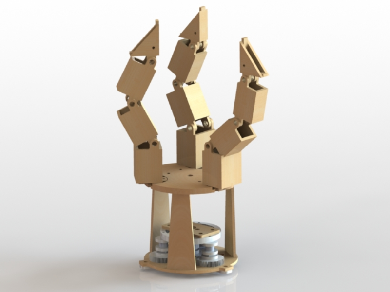
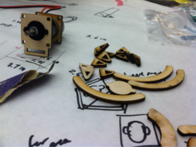
During the first iteration, during which lasercutting plywood and delrin was the main production method, we used epoxy on comb joints to create the box-like finger segments, as seen in Figure 3. The finger segments were mounted on top and within each other to constrain the next segment laterally. These were allowed to pivot about a bolt and spacer that allowed for the finger to curl. Each finger was bolted onto an adjustable peg that could rotate and lock in place with M4 bolts to allow different finger orientations. This initial design was intended to allow the hand to pick up both spherical objects as well as irregular objects such as water bottles by adjusting the amount of contact area between the finger and the object. Another structural characteristic that contributed to grasping objects was the addition of “fingernails” to the tip segment of the fingers. This would be revisited in the final iteration of the hand. The three struts of the first iteration were placed between the top and base plates via mortise and tenon joints as well as sheet metal L brackets, which bolted into place. These contributed to a very sturdy structure over all but added quite a bit of weight to the overall design in hardware. In order to mount the rather large-in-diameter hand to the smaller diameter of the wrist, a small plate was bolted to the arm and then enabled the hand to be bolted to this adapter.
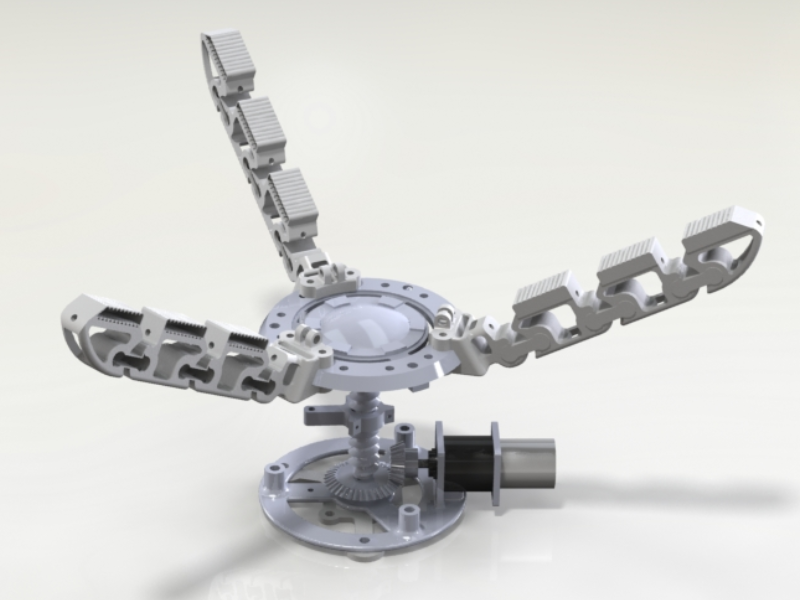
The second iteration was to be made entirely out of 3D printed PLA, polymer, and hardware. We aimed to make this hand Iron Man themed, which is mainly shown by the palm. Although completely new methods of fabrication, we were able to more creatively design parts for this assembly that could not be easily manufactured from planarly cut plywood or delrin. The second iteration attempted to utilize a polymer spring that was shown during class. However by using a “dog bone” shaped polymer between the finger segments, we concluded that there was too much torsional motion to properly grasp and hold an object as we intended. A softer polymer was also used on the inside grasping surface to provide more of a friction hold on the objects. We encountered difficulties mixing correct portions of polymer however and the resulting fingers were not as aesthetically appealing as intended. This iteration also attempted to mount the fingers at a 60 degree angle in order to allow the hand to grasp larger objects. This however, made the previous iteration’s adjustable pegs difficult to implement. Instead we designed a curved C bracket that would be the integrated into the base finger segment and be able to slide around the circumference of the circular top plate. In practice, the adjustability of finger orientation became hindered by the standoffs that were used to connect the top plate to the bottom plate. The same adapter design was used to attach the hand to the arm but we noted that the 3D printed PLA could be used in more creative methods than a simple flat part to mount the hand.
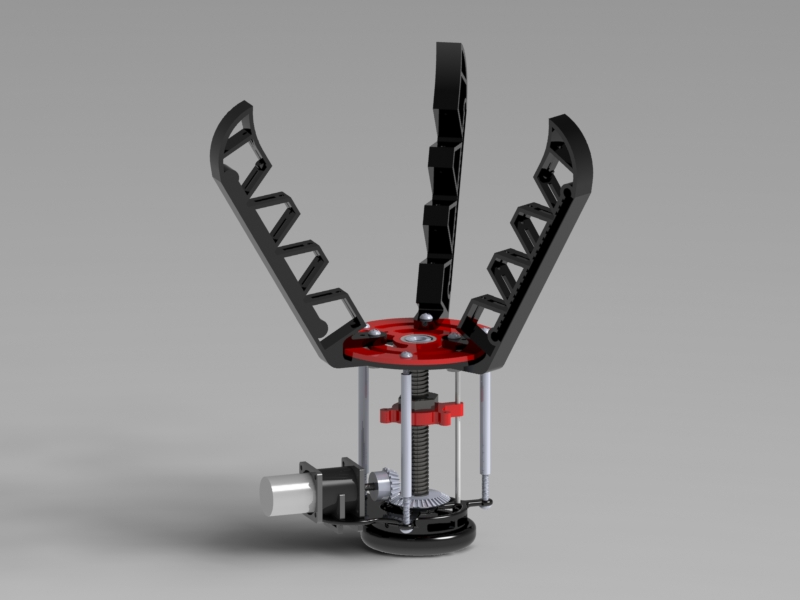
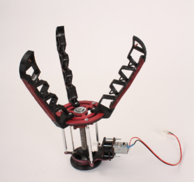
Our third and final iteration attempted to filter out all the issues of our previous iterations and keep the portions that we had found to work well. After further exploring the flexibility with which we could design parts that would be fabricated with 3D printing, we designed a “jam-jar” style threaded adapter,which consists of two threaded halves, that would mount to the robotic arm using M-4 bolts and enable the rest of the hand to simply screw onto the arm. The base that has the mounting features for the transmission has a threaded male end while the female end attaches to the arm. This design not only reduces hardware, but it also allows for a quick and simple way of mounting the hand on the arm.
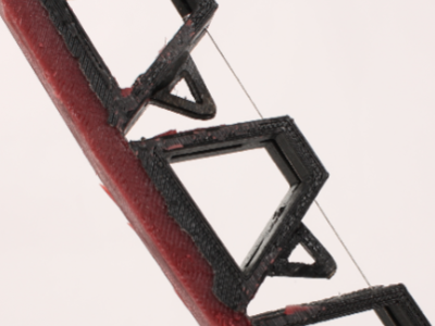
To further simplify the design, we also sacrificed the adjustability of the finger positions and mounted them at static 120 degrees intervals on top of the palm. The C-clamp design was maintained but able to be thinned down to meet material constraints and the fingers used a single, long, polymer backbone instead of multiple springs or separate “dog-bone” polymer connections. The segments however, remained separate but now have guiding “fins” that prevents the torsional slop that was evident in the second iteration. To prevent a messy assembly process, the hand also utilizes a thin layer of "painted on" polymer on the front face of each joint as a higher friction surface between the finger and the target object. A claw design was implemented as a modification of the fingernails in the first iteration to improve grasping. From McMaster-Carr, we were able to find fitting standoffs to hold the top and base plates together and allow for an adjustable amount of space in accordance to the size of the transmission. The goal for the third prototype's aesthetics was to emulate the mechanical talons.
Transmission
Our hand’s transmission is a cable driven design that was modified throughout the three iterations but maintained its start from a small DC motor mounted between the two structural plates and end at the fingertips of the hand.
In the first iteration, the motor, located in the center of the transmission, is connected to a planetary gearset at the sun gear. Three separate spools, each attached to a separate planet gear, would pull the cables crimped to the end of the fingertips. While this was in theory, a simple transmission design, the spool design enabled for a considerable amount of slop and was not structurally reliable. The cabling of this first iteration was also too close to the pivot points of the finger segments, which resulted in stalling the motor. Underactuation in this first iteration was made possible by the linear springs attached between finger segments. The purpose of the springs was to pull the fingers back to the rest position. Although the weakest available were used, the required torque for moving all three fingers exceeded the stall torque of the motor, therefore not much movement could be achieved.
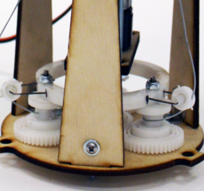
The second iteration attempted to reduce the height of the hand by mounting the motor horizontally and replacing the spur gears to a pair of bevel gears with a 2:1 reduction. The driven bevel gear is connected to a 3D printed leadscrew. The flexibility that the Makerbots provided the design greatly eased assembly. For example, it was possible to create a nut carriage assembly, which had small arms with holes on the end for connecting cable ends. By constraining the leadscrew with the two plates and the nut with the three fixed cables, the nut would only travel vertically, with no rotation. The limitation of the cable driven design was that the positioning of the fingers would have to remain static. Changing the orientation of the fingers would require adjusting the lengths of the cable, which would in turn cause the transmission to provide uneven tensions in each cable. However, we were willing to sacrifice the parametric design of the finger for a well functioning transmission system. Polymers were used in place of springs in this iteration reduced the required torque. However, this became an issue as the spacing between the segments were too far apart and the fingers torqued around the object instead of grasping it in the intended orientation.
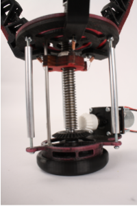
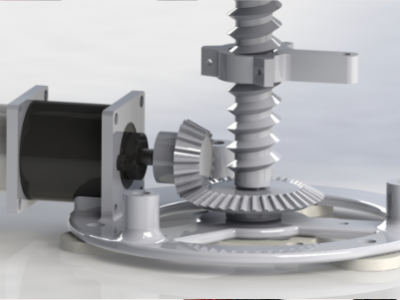
Our final iteration has a set of 90 degree bevel gears with the same 2:1 reduction leading the motor to a lead screw. However, this iteration uses an actual lead screw and nut obtained respectively from the mechanical engineering stockroom and McMaster-Carr. The cables are crimped to the nut carriage, which consists of three layers of eighth inch plywood surounding a nut, and are fed through guide holes up on the inside edge of the fingers and crimped again to the inside of the fingertips. Tension on the cable increases as the nut is moved down the lead screw causing the fingers to curl inward and provides the grasping motion of the hand. The polymer of this iteration is a continuous backbone along the finger and serves as both a hinge and a restoring force to keep the hand in an open position whenever the cable is tensioned. A series of guiding “fins” and slots are used to prevent unwanted writhing of the fingers when grasping an object. The final threaded rod system is very clean and difficult to backdrive the motor but is slow, taking a full 8 seconds for full actuation of the hand.
Power
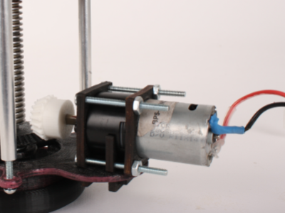
The source of motion of the hand is a Vigor Precision R280 motor with a BO-P5 planetary gearbox. Its maximum efficiency speed is 111 rotations per minute and 0.059 N-m torque. It stalls at 0.353 N-m but with its 1:140 gear ratio is very difficult to backdrive, thus making it sturdy enough to survive the testing of three iterations. The motor has a d-shaft that is mounted into a bevel gear that is mated with another, larger one which turns the lead screw, driving the transmission of the hand.
Fabrication
Our final design relied mostly on 3D printed material which presented its own set of challenges, including fitting all the parts within the material constraints of 100g for our final iteration and accounting for varying tolerances across three different Makerbot 3D printers. A constant trade off for material constraints was sacraficing the structural integrity of parts or the inclusion of entire parts into the final assembly. A stipulation of the project was to include support material but not rafts into the amount of PLA used in the iteration of the prototype. Another difficulty of using the 3D printed parts was the removal of the support material since the Makerbots use the same filament for both the part itself and the support material. Cracking off the supporting portions of printed parts often threatened to break the part itself. The tolerances of 3D printed material were also far more variable than the uniform kerf of the laser cutter and often undersized the intended holes, thus resulting in sanding down holes and reprinting certain parts. Sanding down parts however, risked the structure of the part since the insides of the parts are hollow honeycomb structures to preserve material.
A valuable and fortunate portion of our fabrication was the customizability of the parts we used in our final prototype. With members of the team trained on multiple machines in the shop, we were able to turn down the final lead screw to the exact dimensions needed. 3D printing, while difficult to get exactly right, allowed our group to design parts that could not be made in either the machine shops or with the planar material available.
Finally, a very important part of fabrication was the order of operations that allowed for everything in our hand’s design to be fully integrated with each other. Most of this however was learned through trial and error during final assembly.
Future Improvements
The fabrication and assembly of the hand requires more thought and effort than anticipated. We have improved on this issue since the first iteration. We really had to consider the integration of parts and order of operations for assembly. Here are some general tips we would recommend:
- Leave room for inserting hardware. Tolerances may change due to manufacturing method. There should be enough room to use a conventional tool for the fastener
- Check designs prior to fabrication to make sure parts are integrated well and to ensure the the correct version of parts are created.
- Purchase parts when necessary. It’s easier to buy stock gears rather than printing them for the transmission to operate smoothly.
- Leave time to do testing. Even with the first two iterations, testing can help verify, correct or change designs.
Through our design iterations, these are the more specific improvements we would consider if we had the opportunity to create another prototype:
- Integrate sheet metal fingernails for picking up smaller and possibly flatter objects.
- Spend more time on design to figure out finger geometry that would not interfere too much.
- Figure out how to use polymers effectively to get consistent end products. Account for proper curing time.
- Have a more rigid and assembly-friendly method of attaching the top and bottom halves of the hand.
Aside from creating the physical prototype, we have a few tips on teamwork and organization:
- Have a good project manager to make sure that processes happen on schedule.
- Make sure each team member is responsible for a portion of the hand for an even work distribution.
- Team members should communicate for integration, debugging problems, and to be more productive.
- Be more aware of lead time for fabrication and part orders to be more efficient at assembly.