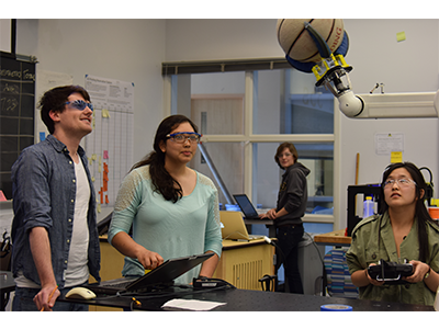
Introduction
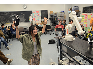
In this project, our team was assigned the task of designing and building an underactuated hand through an iterative design. An underactuated hand is powered by one motor, but has more than one degree of freedom. In each iteration, the material and fabrication technique varied to explore the different methods of rapid prototyping. After creating three prototypes, the final hand was entered in a competition with other hands from this class. The performance of each hand was judged on size, mass, dexterity, and aesthetic appeal.
Design Overview
The goal of our project was to design a hand that can grab several objects ranging in size and shape. To accomplish this, the hands were designed to conform to the object it was picking up and have interchangeable parts that gave the hand variability. Once polyurethane rubbers were introduced to the project, the design goal expanded to include innovation and learning more about soft robotics. In addition to this, the hands were designed to have an assembly process that wasn’t very labor intensive
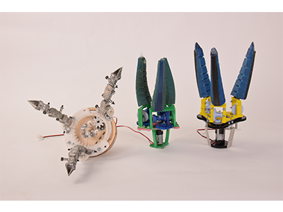
The first iteration of the hand was a three finger cable driven design created out of sheet metal and plywood. This design utilized a servo that could rotate a finger allowing the hand to adjust to the shape of the object it was picking up. Unfortunately, this iteration took well over a full day of work to fabricate all of the bent sheet metal pieces. Assembling the hand was also very labor intensive and difficult. In this design there were a lot of problems with routing the cable because the cable would get caught between the moving finger joints.
The next prototype took a new direction with the project. This iteration still utilized a three finger cable driven design, but the materials used were PLA (polylactic acid) and polyurethane rubber. With these materials we created a new bio inspired design to resemble the shape and movement of a squid’s tentacle. To do this, rubber was poured into 3D printed molds made out of PLA.The purpose of this iteration was to become more familiar with poly urethane and explore soft robotics. To change the range of objects the hand could pick up, the angle the fingers were mounted out could be changed by swapping out the mount. This gave the hand the ability to change how close the fingertips would be when fully actuated. In this hand, fabricating the fingers took several days because the polymers needed to fully cure but did not take a lot of labor. Actually assembling the hand was much quicker than the first iteration .
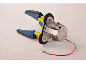
The final prototype was very similar to the second iteration but with some slight modifications. The fingers were still made out of rubbers which gave it the ability to conform to objects easily, and now have fingertips to grip small objects. While fabricating the finger still took several days, assembling the hand was much easier because of an altered structure in the transmission.
Structure
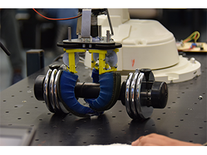
Our final hand is made up of 5051 aluminum sheet metal, ¼” and ⅛” Delrin, 3D printed polylactic acid (PLA), and polyurethane rubbers. In order to achieve a robust hand structure the primary structural member, the palm plate, is comprised of four identical sandwiched plates. The outer most plates are 5051 aluminum sheet metal, the inner plates are ⅛” delrin. The transmission sits between these two plates.
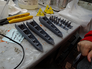
The hand is actuated by compliant finger-like structures composed of two polymers of different shore value, Vytaflex 10 and 60. The differing hardness levels allow the fingers to actuate and spring back after actuation. Additionally there are six 3D printed Polylactic Acid (PLA) “bones” within the fingers to guide the cable from the transmission system to the tip of the finger. We’ve also included flat pieces of PLA to act as fingernails. The plastic structure provides enough reaction force to pick up small objects. Without this structural component, the polymer would not be able to grasp onto small objects.
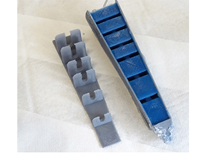
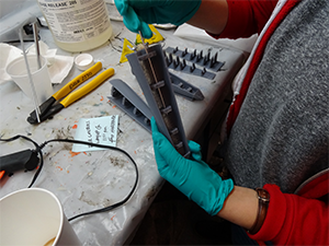
Each finger is made from 3 molds - one inner mold which includes the finger’s bones, and two outer molds to shape the curvature of the fingers. We wanted to include air pockets in the finger so that they can have greater bend angle. Therefore in one of the outer molds, we placed triangular prism like structures extruding out of the wall. In order for the fingers to be composed of different polymers, a 2 step pour process is required. We placed a sacrificial wall to hold the shape of the first poured polymer - Vytaflex 10. The idea is to first cure the Vytaflex 10 polymer then remove the wall so that when the second polymer (Vytaflex 60) is poured it can cure and adhere to the Vytaflex 10 rubber.
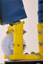
In order for the fingers to come to a point when actuated, we tuned the initial tension of each cable. The cable tension can be adjusted by disassembling the top platform from the mount so that the bevel gear can be placed with the appropriate amount of tension. Initially when the entire mount was one part, we had to disassemble the bolts holding the transmission. By making the mount two parts, one to interface to the fingers and the other to interface to the transmission, we were able to tune with ease.
Transmission
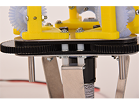
Our fingers are driven by 1/64” steel cable. The cable is crimped to a structural member in the top of the finger mold. These cables integrate with the transmission by crimping to three spool bevel gears. These gears interface with a respective bevel gear that is parallel to the palm plate. The bevel gear integrates with the rest of the transmission via a ¼” D-shaft. The transmission is sandwiched between two delrin plates that were laser cut in order to achieve accurate center-to-center spacing. The main transmission is a planetary gear box. The axial symmetry of the planetary gearbox easily drives the fingers which are spaced 120 degrees apart about the palm plate. The total reduction from motor to bevel gear is 8:1. Our power system is unique in that it combines a planetary gear box system with a cable driven design.
Power
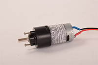
Our hands are powered by a vigor precision BO-P6 motor with an R280 planetary gearbox. This motor is rated for 3v and has a maximum torque of 3.6kgf.cm. We operated the motor at 5v and thus gained a higher torque. The motor is attached to a 3D printed gear with a press fit D-shaft.
Fabrication
The fabrication process depended heavily on careful planning in printing parts on the MakerBot as well as accounting for cure times for the molds. Therefore we laid out a schedule to accommodate for all of the printing and cure times.
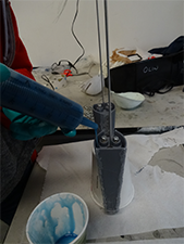
When all mold components were printed, we followed a series of steps before actually pouring in the polyurethane. First, we removed the support material resulted from 3D printing. Sequentially, we brushed a layer of mold release on the mold, everywhere but the bones. We then inserted the hollow rod with the cable into the bones of the mold. Once the cable was crimped, we attached the inner and outer mold together and set it upright with a jig. Polyurethane rubber of shore 10 was then poured into the mold. Once this cured, the sacrificial wall was removed, leaving the bones of the mold inside of the rubber. Another supporting wall was glued on to create a channel along the back of the finger and filled with shore 60. This was the spine of the finger, which acted as a spring.
Future Improvements
While our hand was successful and was able to pick up several objects, there is a lot of room for future improvements. During the final competition, when the hand picked up heavy objects the cable inside of the fingers snapped. This can be easily fixed by replacing the cable with cable of a thicker gauge.
When pouring the polymers in the molds, the method used was very inefficient. The support wall that kept the mold together had to be hot glued in place each time. If there was a small gap, the polymer would seep out of the mold. Whenever this happened, more polymer had to be added later to create a finger of full length.
Another issue was found in the transmission. The gears would skip if there was too much force on the cable. This caused the gear on the spool to lift off the bevel gear. A way to improve this is by fully securing the spool mount to the base plate with more hardware. Another reason the gears could have skipped is the material they were made out of. These gears were made from 3D printed plastic which produces very brittle gears that have a lot of friction. Had the gears been created from a material more smooth, there could have been a lower chance of error.