Project Overview
For the third and final underactuated hand project, we were required to build hands that met a wide array of performance criteria. A stellar hand will be able to pick up heavy objects relative to its weight, grasp very large and very small objects, successfully pick up a number of strange objects such as a bar of soap or a key, and look aesthetically pleasing. Our hand focuses on picking up very large and small objects by using both large and small fingers.
We can pick up objects from the front, in a scooping motion, or from the top in a grasping motion. Springs on each finger ensure that the fingers curl up when the motor is run, then uncurl back to the rest position as the motor is reversed. For the competition our hand was mounted on a robotic arm, operated by Robotics II class members, and attempted grasps on a large array of objects.
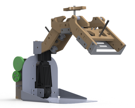
Left - Full CAD of our hand in its final form
Design Thoughts and Decisions
In order to pick up large and small objects we created two different regimes of motion. By driving the motor forwards and backwards, we activate two different motions. One makes the large finger curl in, which can have two effects. If you are picking up a large object, like a volleyball, the finger curls around the ball and clamps it against the base plate. Alternatively, if you are picking up a small object, like a key, the large fingers curls in and scoops the key onto the base plate. Then we can drive the motor in the other direction, lower the small finger, and clamp the key against the base plate.
The design stands out from the others because it it only actuates one finger at a time, and only ever grips with one finger. Unlike a typical hand grasping motion, which pinches objects between the fingers, this hand makes use of a fixed plate to immobilize objects and pick them up.
In our last hand iteration, we had a small lever on the tip of our finger that swung down onto the base plate as the finger curled, trapping the small object that had just been scooped. We transitioned to an alternating finger design because having the lever at the very end of the finger was really hard on the motor. With two fingers moving at different times the transmission is more difficult, but should put less strain on the motor.
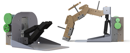
Left - Curling small finger, preparing to compress object on tray
Center - Curled large finger, scooping object into tray
Right - Uncurled large finger, curling small finger
Structure
The primary structural element of the hand is metal tray which resembles a household dustpan. The dustpan's angled walls add structural strength and also prevent circular objects from rolling out. At the top of the duspan are two flanges which the large finger mounts to. There are two additional flanges near the base of the dustpan for the small finger.
The large finger, shown below, is made of plywood and sheet metal and has three joints. It's actuated by adjusting the tension on a cable that functions as a tendon and runs the length of the finger. When tension is applied to the cable, the finger rotates downard and then curls, which allows it to scoop objects onto the tray as illustrated in the Design sub-section. When tension is decreased, springs between the finger joints (well visible in the picture of the large finger) return the finger to its open position.
The small finger has two joints and is made of 3-D printed ABS plastic. Unlike the large finger, it is not exclusively cable-driven - it also employs mechanical linkages. The effect this has is that when actuation begins, the entire finger rotates until the first joint is stopped by the object it is grasping. Because of the mechanical linkages, the second joint continues rotating, effectively wrapping around the object until it too is stopped, at which point the object is immobilized.
Attached to the back of the dustpan is an enclosure made of sheet metal and plywood which has holes that allow the hand to mount to a robotic arm. This enclosure also houses a motor which actuates the fingers. The motor actuates the large finger by winding the tendon cable around the motor's shaft, adjusting its tension. To also actuate the smaller finger, the torque of the motor is transmitted by gears to a secondary shaft at the base of the hand (further detailed in Transmission), which winds in the small cable tendon as it is driven.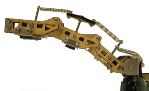
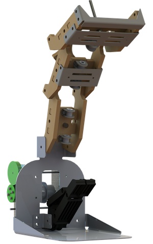
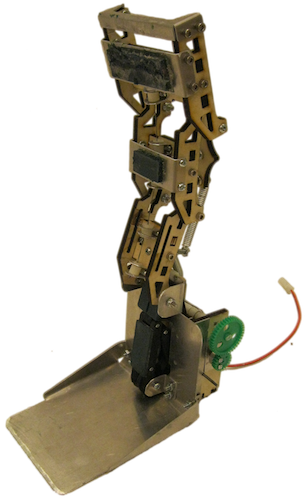
Left - Fully constructed hand, in the rest position
Right - Large finger, with joints, segments, and springs shown
Transmission
The transmission of this hand is perhaps its most interesting feature. It is designed so that when the motor is actuated in one direction, one finger can be completely opened and closed, and in the other direction, the other finger can also be completely opened and closed. The result is that at any one time, only one finger is in motion.
As aforementioned, each finger is actuated by its own shaft and tendon system. The upper shaft is directly connected to the output of the motor, and the lower one is driven by a series of gears. When one shaft turns, the other turns as well.
The means by which the motion of the two fingers was decoupled was simply by building enough slack into the cables that the actuation of one finger did not actuate the other. For example, when the large finger is fully closed, its tendon is fully tensioned. Meanwhile, the small finger's tendon has maximum slack. As the large finger is opened, the slack in the small finger's tendon is gradually taken up. At the moment when the large finger eventually reaches the fully open position, all of the slack in the small finger's cable has been taken up, and it begins to actuate, while slack is gradually added to the large finger's tendon.
The slack occured at the correct times because we measured how much cable it would take to wind each finger in and wound that amount around the opposite shaft. Therefore as one finger drew in, our wrist would let out the same amount of cable on the opposite finger as slack. We didn't end up using the dual-finger system in competition, because our original design goal of immobilizing an object didn't line up exactly with the competition definition of grasp, but we were pleased with its performance - separating the two motions on our hand was a point of pride.
Power
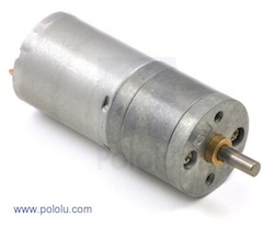
The source of power in the hand is a small DC motor with a 499:1 gear box attached to it, seen right. The motor is powered by electricity and moves with rotational motion. Rotational motion is used initially because it is easy to achieve with the help of a motor and it is efficient. The particular motor that we used is seen in the figure on the right. This motor is quite compact and outputs a significant amount of power in the form of rotational motion. The shift from rotational to linear motion occurs because of the way that motion is transferred to the finger pieces. As the motor spins, it winds the cable, pulling the fingers in. This acts much like the tendons in a hand, and is discussed more in the transmission sub-section.
Some problems did arise in the past prototype design with this motor due to the weak gears inside the gearbox. The motor stalled once, which caused some of the gears inside the gearbox to break. We fixed this in the third iteration by gearing down the motor - now the cable winds in slowly but can apply a greater force before stalling.
Fabrication
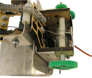
Though we remained true to our original design for most of the fabrication, there were a few cases in which we had to modify this design. These modifications occurred primarily in the design of the transmission. The most important change made was the inclusion of 3/8" diameter nylon spacers along the cable winding shafts. This allowed the fingers to be actuated three times more quickly when compared to the original plan of wrapping the cable around the shaft directly. Four spacers were attached to each winding shaft with epoxy, as seen to the left.
In addition to the inclusion of the nylon spacers, we had to rethink our method of attaching the gears to the winding shafts. At first, we press-fit the gears onto the shafts and then dabbed some epoxy around the connection. However, the epoxy did not bind well to either the gears or the shafts, and there was no epoxy connection between the mating faces. This resulted in a connection that tended to slip when high torques were applied. In order to overcome this problem, we removed the gears and roughed the mating surfaces with a small file. This allowed the epoxy to bind to the two parts more easily and enabled an epoxy bond between the mating surfaces. After this modification, gear slippage was no longer a concern.
There was one non-transmission modification that had to be made due to a fabrication error. During the fabrication process, the base plate was bent in the wrong order, resulting in an improper spacing of the mounting holes above the bottom of the part. In order to preserve the positioning of the small finger, we had to fabricate new mounting plates for the small finger.
Future Improvements
Although the motion of our hand worked as we designed it to, and we did well in the final class competition, there were a number of objects that our hand wasn't well equipped to grasp. Our hand was particularly well suited for a pencil and a volleyball, for example, but the dual finger design would not have worked on a ball bearin. We were lucky that the competition rules allowed a grasp without compression - lifting the object off the ground was enough. For the dual finger design (the large finger scoops an object onto the base plate and the small finger immobilizes it) the large finger had trouble pushing objects back far enough for the small finger to clamp, a problem that was even worse when we were trying to compress, say, a water bottle. Because the small finger must curl around the bottle to compress it, it has a very limited range along the base plate and the water bottle has to be near the back. In the future we would work to extend the range of the small finger, so that it would be easier to compress objects.
One motion of our hand that wasn't quite as we designed it was the scooping motion. The large finger was supposed to swing down, collide with the ground, then continue to pull inwards while dragging across the ground. This dragging motion would be pushing the tip of the finger hard against the table and would keep objects from escaping. Instead, our large finger curled up at ground level, but without really pressing against the ground. Future fixes would require a different tensioning of the springs, so that it took more force to start the curl - that way the springs would be pushing the tip of the finger onto the table.
Future tips for teams, short and sweet
1) Design for your materials. Plan which bolts/springs/adhesives you will use from the beginning and include them in your CAD. This will (help) prevent collisions
2) Pay attention to your motor, and actually look at how fast it will go, how much torque it will give, etc. This is an important design step that we didn't really take part in.
3) Know that if you have slack in the cable, it will twist in strange ways and get caught in places you didn't expect.
4) Seriously, try and take assembly into account when you're designing the part.
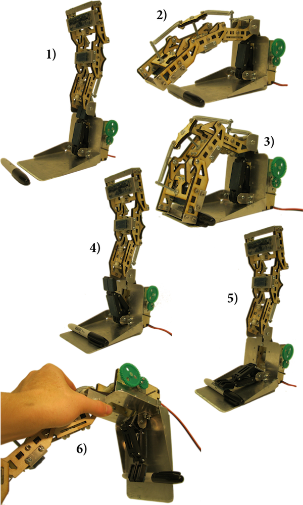
Movement of our Hand
Here you can see each motion of our hand, as it was originally designed. It starts out in the rest position, then curls over the small object it we are trying to pick up. The large finger scoops the object onto the base plate, and then the small finger compresses this object in a steady grasp. As you can see in the final picture, this grip immobilizes the object for further manipulation.