Introduction
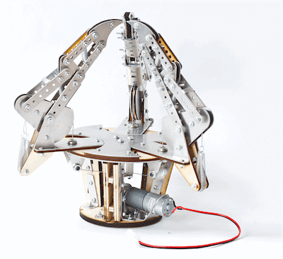
We set out in two months to iterate through three prototypes of an underactuated hand - first using RP thermoplastic, then sheet metal and plywood, and finally a combination of the three.
A mechanical hand is underactuated when it has more degrees of freedom than means by which it is powered. For our hand, one motor controls the movement of one point on the base of each of three linkage fingers via a cable. The fingers of the hand are designed such that as the hand closes, the object the hand is grasping obstructs the movement of parts of the finger, causing the joints to bend inward, making the finger curl in.
Our design was limited to one 12x15in birch plywood sheet (1/4in thickness), one 12x15in birch plywood sheet (1/8in), one 12x12in sheet of sheet metal, $30.00 worth of RP Thermoplastic, any length of steel cable, and one motor.
Within these constraints (mostly), we designed and built a hand that will compete in the following areas:
Grasping Envelope
Dexterity
Aesthetic Appeal
Object Mass : Hand Mass
Design Overview
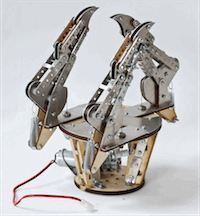
Our design is inspired by the design described in "Underactuation in robotic grasping hands" (Thierry et. al.). This design couples a motor and linkages to produce underactuation in a robotic hand. We used similar geometrical relationships when designing the finger linkages, as we saw this design as stable, predictable, strong, and interesting to fabricate.
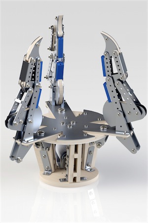
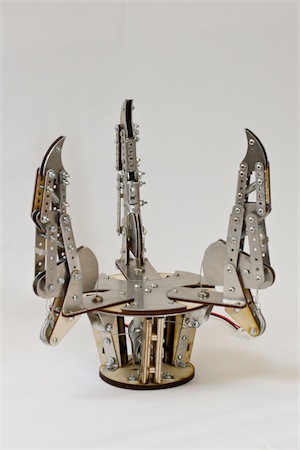
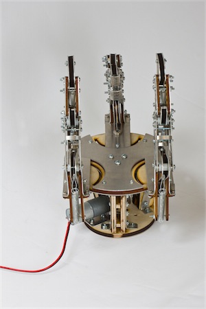
Our design uses sheet metal and plywood to form a cage and finger assembly in an aesthetically-attractive orientation. We designed specifically for the hand to be competitive in all areas of the final competition, but with its best performance being in the weight:weight competition, as well as in its ability to pick up varying shapes of objects - all the way looking good doing it.
We accomplished this by designing for strength, variability, aesthetic appeal, and ease of assembly. The result was a large, (we think intimidating) hand with three fingers that function at independently adjustable angles. This allows for the hand to pick up objects of a variety of shapes and sizes. Cables actuate the fingers, and are hidden from sight as much possible so as not to interfere with the grasped object, or be seen as unsightly mess.
We originally planned to include polymer finger tips and grips (three for each finger), but molds unfortunately were not printed due to a malfunction with the 3D printer.
Structure
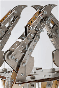
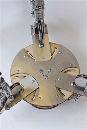
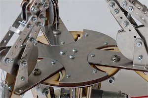
In our final prototype, we decided to design a hand whose focused strength was its ability to pick up objects of different geometries, as well as heavy masses. We decided to, as with previous designs, use three figners, each extending approximately five inches above the main structure of the hand. We decided to space the fingers equally apart across the top platform of the cage, and designed a set screw system that allows the fingers to rotate. Each finger swings on a platform that, once in position, can be held in place with a setscrew that goes through the top platform of the cage. With this rotation, we can orient the fingers for best interaction with object of different geometries - like a sphere, cylinder, cube, or dumbell.
Each component to the finger linkages is made up of .05in sheet metal, though some fingers contain extra support layers of 1/8in birch plywood. We decreased the weight in each of the fingers by adding less plywood supports in each linkage in hopes of being more competitive in the weight:weight ratio of the competition. Each component of the finger linkages has a patter of holes that work as adjustable spring mounts.
The cage was designed for strength and simplicity. The cage is basically two circular discs mounted to each other by wooden legs. The platforms are about 4in apart, and the three legs supporting them attached to the platforms with custom L-brackets the follow the angle of the sloped legs. On the smaller platform, a sheet metal motor-mount contstrains the motor, which turns indefinitely to power a pulley system with three cables attached. The cables run up the center of the cage to a triangular piece of sheet metal (bolted to from the other side of the top platform), which directs the cables outward to each finger.
Underneath each finger mount is a pulley mounted to the finger mount with a sheet metal bracket. The bracket geometry, when aligned with the inside sheet metal layer of the top platform, prevents the mount from spinning, while one bolt connects it all to the finger mount. Each cable runs around the pulley and through a hole drilled in each of the bolts. The cables were then crimped in to a loop and wrapped through the finger to the outer edge of the base of the finger. A spring is placed from this loop to the cage. The cable is then secured in place with a washer and screw.
Power
Power was provided by a cylindrical, 2.28” x 0.98” x 0.98” brushed DC gearmotor with a 499:1 metal gearbox and a 4 mm-diameter D-shaped output shaft. At 6V, the motor runs at 12 RPM, and can be used in continuous rotation.
Transmission
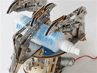
Power was supplied by a motor mounted to the bottom platform of the cage. Cable was attached to a pulley mounted to the motor shaft, so as input was given, the motor would respond, rotating the pulley to either increase or decrease tension in the cables. The cables run up the center of the cage to a plate that redirects tension towards a pulley underneath each finger. These pulleys direct the cable up through a hole in the top platform, where they are attached to the finger base. As the motor applies tension to the cables, they pull down on the finger base, causing the finger to curl inward. A restoring force is applied to the finger components by way of springs that return the fingers to their original positions. As a result, when rotated in the opposite direction, the motor decreases tension in the cable, and the springs pull the fingers back in place.
Fabrication
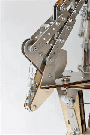
Fabrication of the hand went relatively smoothly. We had designed for polymer grips to be placed on each finger, the fabrication of which required a thermoplastic mold. Because the RP printer wasn't functioning for a period of time, molds were not printed, and grips were not produced. This was our biggest setback, but in practice turned out not to be a make-it or break-it hinderance.
Sheet metal bending was relatively straight-forward, and took relatively little time to complete. Our motor-mount was surprisingly easy to bend, as it required a 120degree bend to align the motor properly. To make it work, we made a folded-paper pattern cut at 120degrees to know when to stop bending the sheet metal. This proved to be an effective way to get fairly accurate bends. All other sheet metal was bent at 90degrees, and the process for each component was carried out smoothly.
Fingers, as previously experienced, were the most meticulous components to assemble. Washers that were added between components to reduce friction and stablize the parts were somewhat frustrating to add, but a pair of tweezers, a little patience, and a steady hand did the job just fine.
We had anticipated some difficulty with drilling holes through the bolts that carry cable from the fingers to the inside of the cage, but after doing so, no structural issues were encountered, and the whole system runs quite smoothly.
Our final design is similar to our previous structurally, so putting it together culminated from lessons learned in the previous hand, and we've developed a very effective system for design and assembly using the sheet metal and plywood supplied.
Future Improvements
Our hand, while having a beastly aesthetic, is pretty heavy. In the future, we could investigate ways in which to reduce weight but retain adequate strength. This would help to create better results in the weight:weight competition. Now, the hand picks up the heaviest object, but could weigh more than it needs to.
We also regret not having the opportunity to investigate polymer molding. With the grips we designed, the hand would likely have much more success in picking up smaller objects, as well as objects that are more "slippery." We also, through the process of printing molds and puring, would have gained much more exposure to, insight into, and experience with polymer prototyping.
Gallery
