Introduction
For the final project of our Mechanical Prototyping class, our objective was to design and build an underactuated, robotic hand that would compete against hands designed by the rest of the class on a variety of different levels. We created two prototypes (one out of 3D printed material and one out of sheet metal and plywood) earlier in the semester to help us with the design and fabrication of our final hand. The competition was designed such that the hands would be tested for a variety of different functionalities while attached to a robotic arm built and controlled by the Robotics II class. These functionalities included size of the grasping envelope (the diameters of items the hand can pick up), strength, dexterity, and aesthetic appeal. Our hand is made of sheet metal, plywood, 3D printed material, and polymers. It was designed to weigh as little as possible while maintaining enough strength to pick up heavy objects. It was also designed with the following material constraints: one 12” x 12” sheet of .050” thick 5052 Aluminum, one 12” x 15” sheet of .25” thick Baltic Birch plywood, one 12” x 15” sheet of .125” thick Baltic Birch plywood, 5 cubic inches of RP material, and a small amount of the polymer Vytaflex-10. With this in mind we chose to use a small amount of sheet metal for reinforcement and more plywood and RP material for the areas where strength was less of an issue.
Design Overview
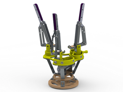
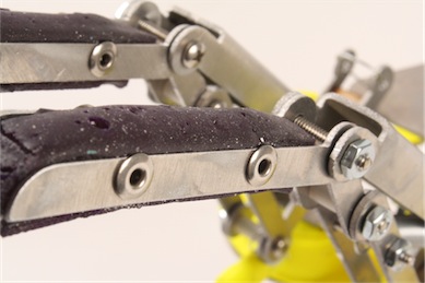
When designing our final hand we considered both of the previous iterations of underactuated robotic hands that we had built to determine the best materials and design for the final project. We decided to use a combination of the materials from the previous hands as well as a combination of the designs. Using RP material (from the 3D printer), sheet metal, and plywood, as well as adding in polymers, allowed us to create a lightweight hand that was also relatively strong. We designed the hand so that the orientation of the fingers can be easily arranged to one of three different configurations to fit whatever object it is attempting to pick up. The fingers themselves are linkages powered by a cable-driven plate. This decision was made to limit the amount of cable threading that had to be done while maintaining constant control of the fingers. The tips of our fingers were designed to be multiple pieces so that the center piece of each fingertip could have Vytaflex-10 molded onto it to add more gripping ability to the fingers. This center piece was then riveted into the rest of the finger. The general design of our fingers was loosely based on an underactuated robotic hand designed at the Delft University of Technology in the Netherlands.
Structure
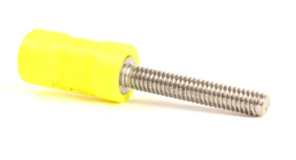
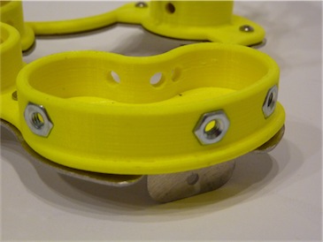
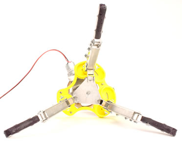 Just as in our first prototype we wanted our final hand to have three different grasp positions; this adjustability enables us to pick up a wide range of objects. Only two of the three fingers need to be adjustable. The base of the hand has raised material that holds the fingers in place and guides them as they are repositioned. To change the positions of the fingers a bolt is loosened that goes straight through the base of the finger and the material around it that holds it in place. Because it’s not a good idea to screw a bolt directly into the 3D printed material, one nut is press fit into the center of the base of the finger, and another one into the side of the raised base around the finger. After the bolt is removed the finger can slide along the base, inside the surrounding material, along the path of a circle, with a center point at the point where the wire pulls the finger lever down. This way when changing position the wire tension remains the same. Another advantage is the wire will always be pulled in the same direction the finger is supposed to close in to. The bolt with 3D printed handle fastens the finger in its new position. The overall structure we wanted to be strong enough, but not bulky, so we added only the necessary material and kept the overall design as light and open as possible.
Transmission
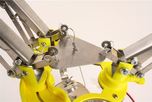
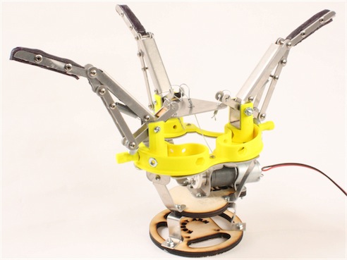
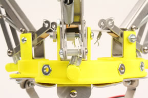
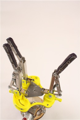
The design of the transmission was one area where we drew a large amount from our previous experiences with our underactuated hands. The first hand we made was driven by cables that acted like tendons for the fingers. This method worked very well but was extremely difficult to deal with during the assembly phase. The cables were difficult to tread through small holes, rubbed on any tension points, and were hard to crimp in the middle of the hand. The second hand we designed was made of linkage fingers that were driven by gears directly powered by the motor. The linkages worked well but we had some issues with the gears that drove the fingers. The main issue we encountered was that the gears were press-fit onto the axles but when the hand was experiencing enough torque the gears would start to shift on their axles. Taking these experiences into account we decided to combine the best of both of our previous designs and created a hand with linkage fingers driven by cables. Each finger is made of two sections that are connected by a freely moving joint. This joint is then constrained by a spring that holds the two sections so that they are nearly parallel. The entire finger is then held in the open position by another spring so that even when upside down it can still grasp objects. The base of each finger is a lever, the front end of which is connected by a cable to a metal plate in the center of the hand. This metal plate is attached through another cable and a plastic pulley to the motor. When the motor runs the entire metal plate is pulled down with all of the inner sides of the levers of the fingers. This causes the fingers to move inwards until they reach the object that is being picked up. When the fingers reach the object the cable continues to pull in but since the first sections can no longer move the springs start to stretch and the upper sections of the fingers bend around the object, locking it in its grasp.
Power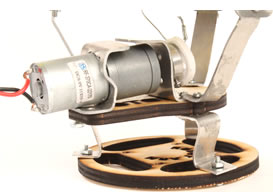
The hand is powered by a brushed DC gear motor. This is a normal brushed DC motor with a gear train built in to reduce the rotation speed of the motor shaft and simultaneously increase the torque. This particular motor has a built in gear ratio of 499:1, which provides a good speed and torque for us so we didn’t need to build an additional gear train. Wires were soldered (tin melted to create an electrical connection) onto the connectors of the motor, and two pins were crimped onto the other end of the wire, to be able to connect the motor to a controller, which is powered by a DC power source. The motor controller consists of a knob you can turn and makes it possible to adjust the speed as well as change the direction of the shaft rotation.The motor is used at a maximum voltage of 6 V, otherwise the generated torque could actually damage the motor. A screw is used to fasten a mounting hub onto the D-shaped motor shaft. This hub has four tapped holes which we used to mount a pulley onto. A wire wraps around the pulley as the motor is powered, which activates the motion of the fingers.
Fabrication
 For this design we incorporated four different methods of fabrication. Parts that needed detail in three dimensions, such as the piece that held our fingers, were rapid prototyped on Olin’s Stratasys. We had to be careful with our choices for parts that would be printed since this was our most limited material, and because of the fact that the ABS is not particularly strong. Shear stresses on parts that are printed by means of additive manufacturing are particularly effective in destroying the structure, so extra thought had to be put in to account for this disadvantage. In order to provide support for some of the plastic, our second method of fabrication was used. Sheet metal that was available to us in .050” thickness was cut on the water jet cutter. In order to keep our hand lightweight and sleek, the aluminum was used for the fingers, backing the ABS, and brackets. Brackets were made in order to attach the different layers of the wrist together, to create a plate for the wires to attach to, and to mount the motor. The third method of fabrication we used was laser cutting ¼” plywood. The wood was used for the piece that mounted the motor and the piece that mounted the wrist to the robot arm. The final manufacturing method we used involved creating the polymers for the fingertips. Since we were tight on time, an accelerator had to be used in our polymer to speed up the curing time. This may have affected the way that the fingertips turned out, though not significantly.
Future Improvements
 Advice that we would give to future designers would be along the lines of looking into other designs of products that are already out there. There are so many resources out there documenting good design concepts that can be used to base designs around. In addition to helpful calculations and analysis, these documents often include mistakes and difficulties that the designers ran into along the way. Understanding other people’s mistakes and learning from them, means you don’t have to make those mistakes yourself. Besides looking at designs that have already been made, there is quite a bit of specific advice we would give. Before finalizing a design, check to make sure that assembly and disassembly is possible, then improve it so that joining members, such as bolts, are easily accessible by your hands and tools. As far as design goes, linkages in the fingers, and tendons for actuation seemed to be the best combination. Hands that used three fingers and were able to reconfigure finger position were much more versatile and worked better than other alternatives.
If we had the ability to make another iteration, there are a few things we would go about changing. First, we would probably give our fingertips some kind of ‘nail’. It was difficult to pick up finer objects with our fingers, unless of course they stuck to the polymer. Having something at the end to dig underneath objects as we picked them up would have been good. We might have also made some changes to the piece that connected all of our wires. There were still issues with fingers being pulled down evenly, especially when positioned in the configuration to grasp cylinders. Another change would have been to make the pulley out of aluminum, rather than using the plastic one. Backing all the wood pieces with aluminum would help for durability of the wrist. Finally, figuring out a more durable system for efficient and smooth tendon pulling would have been a big part of the next iteration.